A1361LKTTN-T Allegro Microsystems Inc, A1361LKTTN-T Datasheet - Page 15
A1361LKTTN-T
Manufacturer Part Number
A1361LKTTN-T
Description
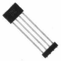
IC,HALL-EFFECT SENSOR,SINGLE-ENDED,BICMOS,SIP,4PIN,PLASTIC
Manufacturer
Allegro Microsystems Inc
Type
Linear - Unipolar, Bipolarr
Datasheet
1.A1360LKTTN-T.pdf
(25 pages)
Specifications of A1361LKTTN-T
Sensing Range
1.4mV/G ~ 4.5mV/G
Voltage - Supply
4.5 V ~ 5.5 V
Current - Supply
12mA
Current - Output (max)
10mA
Output Type
Analog, Ratiometric
Features
Programmable
Operating Temperature
-40°C ~ 150°C
Package / Case
4-SIP
Lead Free Status / RoHS Status
Lead free / RoHS Compliant
Other names
620-1234-2


A1360, A1361,
and A1362
Zone The 136x programming logic is designed to accept up to
two different key-code combinations sequentially without cycling
the supply. The first key-code combination is interpreted as
addressing a register in the first zone, and the second key-code
combination is interpreted as addressing a register in the second
zone. All of the parameter registers are located in either the first
or second zone. The first zone must be entered and exited before
the parameter registers available in the second zone may be
accessed.
Fuse Blowing Applying a high voltage pulse of sufficient dura-
tion to permanently set an addressed bit by blowing a fuse
Programming Pulse Requirements, protocol at T
Programming Voltage
Programming Current
Pulse Rise Time
Pulse Fall Time
Characteristic
Pulse Width
Symbol
V
V
V
t
ACTIVE
t
P(HIGH)
P(LOW)
t
BLOW
P(MID)
LOW
t
t
I
Pr
Pf
Adjustable Bandwidth (50 kHz Maximum) and Analog Output
P
Low-Noise Programmable Linear Hall Effect Sensor ICs with
Measured at the VOUT pin.
Minimum supply current required to ensure proper
fuse blowing. In addition, a minimum capacitance,
C
VOUT and GND pins during programming, to provide
the current necessary for fuse blowing.
Duration of V
V
final V
Duration of V
selection or bit field addressing.
Duration of V
Rise time required for transitions from V
either V
Fall time required for transitions from V
V
BLOW
P(MID)
P(MID)
BLOW
= 0.1 μF, must be connected between the
and V
to V
P(MID)
P(LOW)
A
pulse.
P(LOW)
P(MID)
P(HIGH)
P(HIGH)
or V
= 25°C
.
P(HIGH)
and V
voltage level for separating
pulses for fuse blowing.
pulses, and delay time after the
internal to the device. After a bit (fuse) has been blown, it cannot
be reset.
Blow Pulse A high voltage pulse of sufficient duration to blow the
addressed fuse.
Cycling the Supply Powering-down, and then powering-up the
supply voltage. Cycling the supply is used to clear the program-
ming settings in Try mode.
Notes
.
P(HIGH)
pulses for register
P(HIGH)
P(LOW)
or
to
115 Northeast Cutoff
1.508.853.5000; www.allegromicro.com
Allegro MicroSystems, Inc.
Worcester, Massachusetts 01615-0036 U.S.A.
Min.
300
14
26
40
40
40
–
5
5
Typ.
15
27
–
–
–
–
–
–
–
Max.
100
100
5.5
16
28
–
–
–
–
Units
mA
μs
μs
μs
μs
μs
V
V
V
15
Related parts for A1361LKTTN-T
Image
Part Number
Description
Manufacturer
Datasheet
Request
R

Part Number:
Description:
CONN RECEPT CPC 4POS REV SER 1
Manufacturer:
Tyco Electronics
Datasheet:

Part Number:
Description:
IC, HALL EFFECT SENSOR, Linear, SOIC-8
Manufacturer:
Allegro Microsystems Inc
Datasheet:
Part Number:
Description:
IC, HALL EFFECT SENSOR, Linear, SOIC-8
Manufacturer:
Allegro Microsystems Inc
Datasheet:
Part Number:
Description:
IC, HALL EFFECT SENSOR, Linear, SOIC-8
Manufacturer:
Allegro Microsystems Inc
Datasheet:

Part Number:
Description:
IC SWITCH INTERFACE 2CHAN 8-SOIC
Manufacturer:
Allegro Microsystems Inc
Datasheet:

Part Number:
Description:
IC SMOKE DETECTOR ION 16-DIP
Manufacturer:
Allegro Microsystems Inc
Datasheet:
Part Number:
Description:
IC SMOKE DETECTOR ION 16-DIP
Manufacturer:
Allegro Microsystems Inc
Datasheet:
Part Number:
Description:
IC SMOKE DETECTOR ION 16-DIP
Manufacturer:
Allegro Microsystems Inc
Datasheet:
Part Number:
Description:
IC SMOKE DETECTOR PHOTO 16-DIP
Manufacturer:
Allegro Microsystems Inc
Datasheet:
Part Number:
Description:
IC SMOKE DETECTOR ION 16-DIP
Manufacturer:
Allegro Microsystems Inc
Datasheet:
Part Number:
Description:
IC SMOKE DETECTOR PHOTO 16-DIP
Manufacturer:
Allegro Microsystems Inc
Datasheet:
Part Number:
Description:
IC SMOKE DETECTOR PHOTO 16-DIP
Manufacturer:
Allegro Microsystems Inc
Datasheet:
Part Number:
Description:
IC SMOKE DETECTOR ION 16-DIP
Manufacturer:
Allegro Microsystems Inc
Datasheet:
Part Number:
Description:
IC SMOKE DETECTOR PHOTO 16-SOIC
Manufacturer:
Allegro Microsystems Inc
Datasheet:

Part Number:
Description:
IC LED DRIVER HIGH BRIGHT 16-QFN
Manufacturer:
Allegro Microsystems Inc
Datasheet: