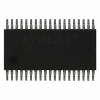
A3938SLDTR-T Allegro Microsystems Inc, A3938SLDTR-T Datasheet - Page 9

A3938SLDTR-T
Manufacturer Part Number
A3938SLDTR-T
Description
IC,Motor Controller,TSSOP,38PIN
Manufacturer
Allegro Microsystems Inc
Datasheet
1.A3938SLDTR-T.pdf
(11 pages)
Specifications of A3938SLDTR-T
Applications
DC Motor Controller, Brushless (BLDC), 3 Phase
Number Of Outputs
1
Voltage - Supply
18 V ~ 50 V
Operating Temperature
-20°C ~ 85°C
Mounting Type
Surface Mount
Package / Case
38-TSSOP
Operating Temperature Classification
Commercial
Package Type
TSSOP
Operating Supply Voltage (min)
10.8V
Operating Supply Voltage (max)
13.2V
Lead Free Status / RoHS Status
Lead free / RoHS Compliant
Current - Output
-
Voltage - Load
-
Lead Free Status / Rohs Status
Compliant
Other names
620-1130-2
A3938SLDTR-T
A3938SLDTR-T
Available stocks
Company
Part Number
Manufacturer
Quantity
Price
Company:
Part Number:
A3938SLDTR-T
Manufacturer:
NUVOTON
Quantity:
2 140
Part Number:
A3938SLDTR-T
Manufacturer:
ALLEGRO/雅丽高
Quantity:
20 000
A3938
each commutation. If a stalled motor results from a fault, the
fault can only be cleared by toggling the RESET pin or by a
power-up sequence.
Current Regulation.
an internal fi xed off-time, PWM-control circuit. When the
outputs of the MOSFETs are turned on, current increases in
the motor winding until it reaches a value given by:
At the trip point, the sense comparator resets the source
enable latch, turning off the source driver. At this point, load
inductance causes the current to recirculate for the fi xed off-
time period. The current path during recirculation is deter-
mined by the confi guration of the MODE and SR input pins.
The fi xed off-time is determined by an external resistor, R
and capacitor, C
to AGND. The fi xed off-time is approximated by:
t
values for t
proper circuit operation, 10 kΩ < R
Torque control can be implemented by varying the REF input
voltage as long as the PWM input stays high. If direct control
of the torque/current is desired by PWM input, a voltage can
be applied to the REF pin to set an absolute maximum cur-
rent limit.
PWM Blank.
to set the BLANK time duration. At the end of a PWM
off-cycle, a high-side gate selected by the commutation logic
turns on. At this time, large current transients can occur dur-
ing the reverse recovery time, t
OFF
should be in the range between 10 μs and 50 μs. Larger
Brake Control
BRAKE
0
0
1
1
OFF
could result in audible noise problems. For
T
The capacitor C
, connected in parallel from the RC terminal
BRKSEL
I
0
1
0
1
TRIP
t
OFF
= V
Load current can be regulated by
= R
REF
Before Power Loss Brake Trigger Event
Brake mode – All low-side gate drivers ON
Brake mode – All low-side gate drivers ON
rr
T
, of the intrinsic body diodes
T
×
/ R
also serves as the means
C
T
SENSE
T
< 500 kΩ.
Normal run mode
Normal run mode
Three-Phase Power MOSFET Controller
T
,
of the power MOSFETs. To prevent false tripping of the
sense comparator, the BLANK function disables the com-
parator for a time period defi ned by:
The user must ensure that C
current spike duration.
Braking.
forcing all low-side power MOSFETs on, and all high-side
power MOSFETs off. This effectively short-circuits the
BEMF and brakes the motor. During braking, the load cur-
rent can be approximated by:
As the current does not fl ow through the sense resistor dur-
ing a dynamic brake, care should be taken to ensure that the
maximum ratings of the power MOSFETs are not exceeded.
Note: On its rising edge, a RESET setting of 1 overrides the
BRAKE input pin and latches the condition selected by the
BRKSEL pin.
Power Loss Brake.
provide a power-down braking option. A Power-Loss Brake
Trigger Event, which is either an undervoltage on VREG
or a RESET = 1 rising edge, is sensed by the A3938, which
then dynamically brakes or coasts (depending on the stored
BRKSEL setting) the motor. The reservoir capacitor on the
BRKCAP pin provides the positive voltage that forces the
low-side gates of the power MOSFETs high, keeping them
on, even after supply voltage is lost. A stored setting of BRK-
SEL = 1 brakes the motor, but a stored setting of BRKSEL = 0
coasts it. The combined effect of these settings is shown in the
table Brake Control.
Coast mode – All gate drive outputs OFF
Brake mode – All low-side gate drivers ON
Coast mode – All gate drive outputs OFF
Brake mode – All low-side gate drivers ON
t
The A3938 dynamically brakes the motor by
BLANK
After Power Loss Brake Trigger Event
I
= 1.9
BRAKEPEAK
×
The BRKCAP and BRKSEL pins
C
115 Northeast Cutoff
1.508.853.5000; www.allegromicro.com
Allegro MicroSystems, Inc.
Worcester, Massachusetts 01615-0036 U.S.A.
T
T
= V
/ (1
is large enough to cover the
BEMF
×
10
/ R
-3
LOAD
– [2 / R
T
])
9


