AD5207BRUZ10 Analog Devices Inc, AD5207BRUZ10 Datasheet
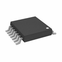
DUAL 8-BIT POTENTIOMETER TAPE AND REEL

AD5207BRUZ10

Manufacturer Part Number
AD5207BRUZ10
Description
DUAL 8-BIT POTENTIOMETER TAPE AND REEL
Manufacturer
Analog Devices Inc
Datasheet

Specifications of AD5207BRUZ10

Rohs Compliant
YES
Taps
256
Resistance (ohms)
10K
Number Of Circuits
2
Temperature Coefficient
500 ppm/°C Typical
Memory Type
Volatile
Interface
SPI, 3-Wire Serial
Voltage - Supply
2.7 V ~ 5.5 V, ±2.2 V ~ 2.7 V
Operating Temperature
-40°C ~ 125°C
Mounting Type
Surface Mount
Package / Case
14-TSSOP
Resistance In Ohms
10K
Lead Free Status / RoHS Status
Lead free / RoHS Compliant

Available stocks

Company
Part Number
Manufacturer
Quantity
Price
Part Number:
AD5207BRUZ10
Manufacturer:
ADI/亚德诺
Quantity:
20 000
a
GENERAL DESCRIPTION
The AD5207 provides dual channel, 256-position, digitally
controlled variable resistor (VR) devices that perform the same
electronic adjustment function as a potentiometer or variable
resistor. Each channel of the AD5207 contains a fixed resistor with
a wiper contact that taps the fixed resistor value at a point
determined by a digital code loaded into the SPI-compatible
serial-input register. The resistance between the wiper and either
end point of the fixed resistor varies linearly with respect to the
digital code transferred into the VR latch. The variable resistor
offers a completely programmable value of resistance, between
the A Terminal and the wiper or the B Terminal and the wiper.
The fixed A-to-B terminal resistance of 10 kΩ, 50 kΩ or 100 kΩ
has a ± 1% channel-to-channel matching tolerance with a nomi-
nal temperature coefficient of 500 ppm/°C. A unique switching
circuit minimizes the high glitch inherent in traditional switched
resistor designs and avoids any make-before-break or break-
before-make operation.
Each VR has its own VR latch, which holds its programmed
resistance value. These VR latches are updated from an internal
serial-to-parallel shift register, which is loaded from a standard
3-wire serial-input digital interface. Ten bits, to make up the
data word, are required and clocked into the serial input register.
The first two bits are address bits. The following eight bits are
the data bits that represent the 256 steps of the resistance value.
The reason for two address bits instead of one is to be compatible
with similar products such as AD8402 so that drop-in replacement
is possible. The address bit determines the corresponding VR
latch to be loaded with the data bits during the returned positive
edge of CS strobe. A serial data output pin at the opposite end
of the serial register allows simple daisy chaining in multiple
VR applications without additional external decoding logic.
An internal reset block will force the wiper to the midscale posi-
tion during every power-up condition. The SHDN pin forces an
open circuit on the A Terminal and at the same time shorts the
wiper to the B Terminal, achieving a microwatt power shutdown
state. When SHDN is returned to logic high, the previous latch
settings put the wiper in the same resistance setting prior to
shutdown. The digital interface remains active during shutdown;
code changes can be made to produce new wiper positions when
the device is resumed from shutdown.
The AD5207 is available in 1.1 mm thin TSSOP-14 package,
which is suitable for PCMCIA applications. All parts are guaran-
teed to operate over the extended industrial temperature range
of –40°C to +125°C.
DGND
SHDN
CLK
V
V
SDI
CS
DD
SS
FUNCTIONAL BLOCK DIAGRAM
2-Channel, 256-Position
LOGIC
RDAC1 REGISTER
A1
Digital Potentiometer
W1
SERIAL INPUT REGISTER
AD5207
B1
R
RDAC2 REGISTER
A2
8
W2
AD5207
POWER-
RESET
ON
R
B2
SDO

Related parts for AD5207BRUZ10

AD5207BRUZ10 Summary of contents

Page 1

GENERAL DESCRIPTION The AD5207 provides dual channel, 256-position, digitally controlled variable resistor (VR) devices that perform the same electronic adjustment function as a potentiometer or variable resistor. Each channel of the AD5207 contains a fixed resistor with a wiper ...

Page 2

AD5207–SPECIFICATIONS ELECTRICAL CHARACTERISTICS 100 k VERSION –40 C < T < +125 C unless otherwise noted Parameter DC CHARACTERISTICS RHEOSTAT MODE Specifications Apply to All VRs 2 Resistor Differential ...

Page 3

Parameter Symbol INTERFACE TIMING CHARACTERISTICS 6, 11 Applies to All Parts Input Clock Pulsewidth t Data Setup Time t Data Hold Time t 12 CLK to SDO Propagation Delay t CS Setup Time t CS High Pulsewidth t CLK Fall ...

Page 4

AD5207 1 ABSOLUTE MAXIMUM RATINGS (T = 25°C, unless otherwise noted GND . . . . . . . . . . . . . . . . . . . . . . . . . ...

Page 5

V = 5.5V 0.15 0.10 0.05 0.00 0.05 0.10 0.15 0. 128 160 192 CODE – Decimal Ω 0. 5.5V 0.15 0.10 0.05 0.00 –0.05 –0.10 –0.15 –0.20 0 ...

Page 6

AD5207 5. –40 – TEMPERATURE – C 160 140 120 100 ...

Page 7

DATA = 80 H –6 DATA = 40 H –12 DATA = 20 H –18 DATA = 10 H –24 DATA = 08 H –30 DATA = 04 H –36 DATA = 02 H –42 DATA = 01 H ...

Page 8

AD5207 120 100 – 128 160 CODE – Decimal ∆ ∆ 2500 2000 1500 1000 500 0 500 0 ∆ 100.0 10.0 1.0 0.1 0 192 224 256 32 64 ...

Page 9

OPERATION The AD5207 provides a dual channel, 256-position digitally controlled variable resistor (VR) device. The terms VR, RDAC, and digital potentiometer are sometimes used interchangeably. Changing the programmable VR settings is accomplished by clocking in a 10-bit serial data word ...

Page 10

AD5207 The data setup and data hold times in the specification table determine the data valid time requirements. The last ten bits of the data word entered into the serial register are held when CS returns high and any extra ...

Page 11

Table IV (DEC Output State 255 10006 Full-Scale (R AB 128 5045 Midscale LSB 0 45 Zero-Scale (Wiper Contact Resistance) Note that in the zero-scale condition a finite wiper resistance of 45 ...

Page 12

AD5207 TEST CIRCUITS Figures define the test conditions used in product Specification table. DUT LSB = V+/ CONNECT DUT DUT I = ...

Page 13

DIGITAL POTENTIOMETER FAMILY SELECTION GUIDE Number of VRs Terminal Interface Part per Voltage Data Number Package Range Control ± +5.5 V AD5201 1 3-Wire AD5220 1 5.5 V Up/Down ± +28 V AD7376 1 3-Wire ± ...

Page 14

AD5207 SEATING OUTLINE DIMENSIONS Dimensions shown in inches and (mm) 14-Lead TSSOP (RU-14) 0.201 (5.10) 0.193 (4.90 0.177 (4.50) 0.169 (4.30) 0.256 (6.50) 0.246 (6.25 PIN 1 0.006 (0.15) 0.0433 (1.10) MAX 0.002 (0.05) 8 0.0118 ...

Page 15

...

Page 16

–16– ...

Related keywords