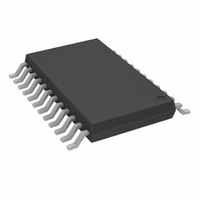
AD7192BRUZ-REEL Analog Devices Inc, AD7192BRUZ-REEL Datasheet - Page 27

AD7192BRUZ-REEL
Manufacturer Part Number
AD7192BRUZ-REEL
Description
2ch VeryLow Noise 24-Bit SD ADC IC
Manufacturer
Analog Devices Inc
Datasheet
1.AD7192BRUZ.pdf
(40 pages)
Specifications of AD7192BRUZ-REEL
Design Resources
Precision Weigh Scale Design Using AD7192 with Internal PGA (CN0119)
Number Of Bits
24
Sampling Rate (per Second)
4.8k
Data Interface
DSP, MICROWIRE™, QSPI™, Serial, SPI™
Number Of Converters
1
Voltage Supply Source
Analog and Digital
Operating Temperature
-40°C ~ 105°C
Mounting Type
Surface Mount
Package / Case
24-TSSOP (0.173", 4.40mm Width)
Lead Free Status / RoHS Status
Lead free / RoHS Compliant
Available stocks
Company
Part Number
Manufacturer
Quantity
Price
Company:
Part Number:
AD7192BRUZ-REEL
Manufacturer:
ADI
Quantity:
1 000
50 Hz/60 Hz Rejection
Normal mode rejection is one of the main functions of the
digital filter. With chop disabled, 50 Hz rejection is obtained
when the output data rate is set to 50 Hz, and 60 Hz rejection is
achieved when the output data rate is set to 60 Hz. Simulta-
neous 50 Hz and 60 Hz rejection is obtained when the output
data rate is set to 10 Hz. Simultaneous 50 Hz/60 Hz rejection
can also be achieved using the REJ60 bit in the mode register.
When the output data rate is programmed to 50 Hz and the
REJ60 bit is set to 1, notches are placed at both 50 Hz and 60 Hz.
Figure 23 and Figure 24 show the frequency response of the
sinc
rate is programmed to 50 Hz and REJ60 is set to 1.
Again, the sinc
than the sinc
achieved with the sinc
When chop is enabled, lower output data rates must be used to
achieve 50 Hz and 60 Hz rejection. With REJ60 set to 1, an output
data rate of 12.5 Hz gives simultaneous 50 Hz/60 Hz rejection
when the sinc
16.7 Hz gives simultaneous 50 Hz/60 Hz rejection when the sinc
4
Figure 23. Sinc
Figure 24. Sinc
filter and sinc
–100
–100
–10
–20
–30
–40
–50
–60
–70
–80
–90
–10
–20
–30
–40
–50
–60
–70
–80
–90
0
0
0
0
3
4
filter. Also, better stop-band attenuation is
4
filter is selected, whereas an output data rate of
filter provides better 50 Hz/60 Hz rejection
4
3
25
25
Filter Response (50 Hz Output Data Rate, REJ60=1)
Filter Response (50 Hz Output Data Rate, REJ60=1)
3
filter, respectively, when the output data
4
filter.
50
50
FREQUENCY (Hz)
FREQUENCY (Hz)
75
75
100
100
125
125
150
150
Rev. A | Page 27 of 40
3
filter is used. Figure 25 and Figure 26 show the filter response for
both output data rates when REJ60 is set to 1.
Zero Latency
Zero latency is enabled by setting the SINGLE bit in the mode
register to 1. With zero latency, the complete settling time is
allowed for each conversion. Therefore,
Zero latency means that the output data rate is constant
irrespective of the number of analog input channels enabled;
the user does not need to consider the effects of channel
changes on the output data rate. The disadvantages of zero
latency are the increased noise for a given output data rate
compared with the nonzero latency mode. For example, when
zero latency is not enabled, the AD7192 has a noise-free
resolution of 18.5 bits when the output data rate is 50 Hz and
the gain is set to 128. When zero latency is enabled, the ADC
has a resolution of 17.5 bits peak-to-peak when the output data
rate is 50 Hz. The filter response also changes. Figure 19 shows
the filter response for the sinc
is 50 Hz (zero latency disabled). Figure 27 shows the filter
response when zero latency is enabled and the output data rate
f
ADC
–100
–100
–10
–20
–30
–40
–50
–60
–70
–80
–90
–10
–20
–30
–40
–50
–60
–70
–80
–90
Figure 25. Sinc
Figure 26. Sinc
0
0
= 1/t
0
0
SETTLE
25
25
4
3
Filter Response (12.5 Hz Output Data Rate,
Filter Response (16.7 Hz Output Data Rate,
Chop Enabled, REJ60 = 1)
Chop Enabled, REJ60 = 1)
50
50
FREQUENCY (Hz)
FREQUENCY (Hz)
4
filter when the output data rate
75
75
100
100
125
125
AD7192
150
150


