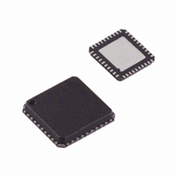
AD8123ACPZ-R7 Analog Devices Inc, AD8123ACPZ-R7 Datasheet - Page 6

AD8123ACPZ-R7
Manufacturer Part Number
AD8123ACPZ-R7
Description
IC,LINE RECEIVER,TRIPLE,DIFFERENTIAL,LLCC,40PIN,PLASTIC
Manufacturer
Analog Devices Inc
Type
Receiverr
Datasheet
1.AD8123ACPZ-R7.pdf
(16 pages)
Specifications of AD8123ACPZ-R7
Number Of Drivers/receivers
0/3
Voltage - Supply
4.5 V ~ 5.5 V
Mounting Type
Surface Mount
Package / Case
40-LFCSP
Lead Free Status / RoHS Status
Lead free / RoHS Compliant
Protocol
-
Lead Free Status / RoHS Status
Lead free / RoHS Compliant
Other names
AD8123ACPZ-R7TR
AD8123
PIN CONFIGURATION AND FUNCTION DESCRIPTION
Table 4. Pin Function Descriptions
Pin No.
1, 10, 20, 21, 30, 40
2
3
4
5
6
7
8
9
11, 14, 17, 22, 33
12
13, 16, 19, 29, 36
15
18
23
24, 39
25
26
27
28
31
32
34
35
37
38
Exposed Underside Pad
NC
Mnemonic
+IN
−IN
OUT
V
OUT
−IN
+IN
V
V
OUT
V
OUT
OUT
V
GND
V
V
V
PD
+IN
−IN
+IN
−IN
+IN
−IN
S+
S−
S−
S+
OFFSET
GAIN
PEAK
POLE
_CMP
_CMP
CMP1
CMP1
CMP2
CMP2
R
R
G
G
B
B
CMP1
CMP2
B
G
R
OUT
V
OUT
V
NC = NO CONNECT
NOTES
1. EXPOSED PADDLE ON THE BOTTOM OF THE PACKAGE
+IN
–IN
–IN
+IN
S+
S–
MUST BE CONNECTED TO A PCB PLANE TO ACHIEVE
SPECIFIED THERMAL RESISTANCE.
_CMP
_CMP
CMP1
CMP1
CMP1
CMP2
CMP2
CMP2
Thermal Plane Connection. Connect to any PCB plane with voltage between V
Description
No Internal Connection.
Positive Input, Comparator 1.
Negative Input, Comparator 1.
Output, Comparator 1.
Positive Power Supply, Comparator. Must be connected to V
Output, Comparator 2.
Negative Input, Comparator 2.
Positive Input, Comparator 2.
Negative Power Supply, Comparator. Must be connected to V
Negative Power Supply, Equalizer Sections.
Output, Blue Channel.
Positive Power Supply, Equalizer Sections.
Output, Green Channel.
Output, Red Channel.
Output Offset Control Voltage.
Signal Ground Reference.
Broadband Flat Gain Control Voltage.
Equalizer High Frequency Boost Control Voltage.
Equalizer Pole Location Adjustment Control Voltage.
Power Down.
Positive Input, Red Channel.
Negative Input, Red Channel.
Positive Input, Green Channel.
Negative Input, Green Channel.
Positive Input, Blue Channel.
Negative Input, Blue Channel.
NC
NC
10
1
2
3
4
5
6
7
8
9
Figure 4. Pin Configuration
1
2
Rev. A | Page 6 of 16
(Not to Scale)
AD8123
TOP VIEW
30
29
28
27
26
25
24
23
22
21
NC
V
PD
V
V
V
GND
V
V
NC
S+
POLE
PEAK
GAIN
OFFSET
S–
S+
S−
.
.
S+
and V
S−
.


