NZ9F12VT5G ON Semiconductor, NZ9F12VT5G Datasheet
NZ9F12VT5G
Specifications of NZ9F12VT5G
Available stocks


Related parts for NZ9F12VT5G

NZ9F12VT5G Summary of contents
Page 1
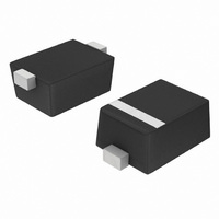
NZ9F2V4T5G SERIES Zener Voltage Regulators 200 mW SOD−923 Surface Mount This series of Zener diodes is packaged in a SOD−923 surface mount package. They are designed to provide voltage regulation protection and are especially attractive in situations where space is ...
Page 2
ELECTRICAL CHARACTERISTICS (T = 25°C unless otherwise noted 0.9 V Max for all types Symbol Parameter V Reverse Zener Voltage @ Reverse Current ZT Z Maximum ...
Page 3
... NZ9F5V6T5G 5 5.32 NZ9F6V2T5G 6 5.89 NZ9F6V8T5G A* 6.46 NZ9F7V5T5G D* 7.13 NZ9F8V2T5G E* 7.79 NZ9F9V1T5G F* 8.65 NZ9F10VT5G J* 9.50 NZ9F11VT5G K* 10.45 NZ9F12VT5G L* 11.40 NZ9F13VT5G P* 12.35 NZ9F15VT5G Q* 14.25 NZ9F16VT5G R* 15.20 NZ9F18VT5G T* 17.10 NZ9F20VT5G V* 19.00 NZ9F22VT5G Y* 20.90 NZ9F24VT5G F 22.80 *Rotated 90°. **Rotated 270°. 1. Zener voltage is measured with a pulse test current 25° ...
Page 4
... H E *For additional information on our Pb−Free strategy and soldering details, please download the ON Semiconductor Soldering and Mounting Techniques Reference Manual, SOLDERRM/D. ON Semiconductor and are registered trademarks of Semiconductor Components Industries, LLC (SCILLC). SCILLC reserves the right to make changes without further notice to any products herein. SCILLC makes no warranty, representation or guarantee regarding the suitability of its products for any particular purpose, nor does SCILLC assume any liability arising out of the application or use of any product or circuit, and specifically disclaims any and all liability, including without limitation special, consequential or incidental damages. “ ...