ADXL345BCCZ-RL Analog Devices Inc, ADXL345BCCZ-RL Datasheet - Page 20
ADXL345BCCZ-RL
Manufacturer Part Number
ADXL345BCCZ-RL
Description
Digital Output Three-Axis Accel 4K RL
Manufacturer
Analog Devices Inc
Series
iMEMS®r
Datasheet
1.EVAL-ADXL345Z.pdf
(40 pages)
Specifications of ADXL345BCCZ-RL
Design Resources
Sensing Low-g Acceleration Using ADXL345 Digital Accelerometer Connected to ADuC7024 (CN0133)
Axis
X, Y, Z
Acceleration Range
±2g, 4g, 8g, 16g
Sensitivity
256LSB/g, 128LSB/g, 64LSB/g, 32LSB/g
Voltage - Supply
2 V ~ 3.6 V
Output Type
Digital
Bandwidth
6.25Hz ~ 3.2kHz Selectable
Interface
I²C, SPI
Mounting Type
Surface Mount
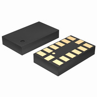
Package / Case
14-LGA
Package Type
LGA
Operating Supply Voltage (typ)
2.5V
Operating Supply Voltage (max)
3.6V
Operating Temperature (min)
-40C
Operating Temperature (max)
85C
Operating Temperature Classification
Industrial
Product Depth (mm)
3mm
Product Length (mm)
5mm
Mounting
Surface Mount
Pin Count
14
Lead Free Status / RoHS Status
Lead free / RoHS Compliant
Lead Free Status / RoHS Status
Lead free / RoHS Compliant
Other names
ADXL345BCCZ-RLTR
Available stocks
Company
Part Number
Manufacturer
Quantity
Price
Company:

Part Number:
ADXL345BCCZ-RL7
Manufacturer:
POWER
Quantity:
14 300


ADXL345
INTERRUPTS
The ADXL345 provides two output pins for driving interrupts:
INT1 and INT2. Both interrupt pins are push-pull, low impedance
pins with output specifications shown in Table 13. The default
configuration of the interrupt pins is active high. This can be
changed to active low by setting the INT_INVERT bit in the
DATA_FORMAT (Address 0x31) register. All functions can
be used simultaneously, with the only limiting feature being
that some functions may need to share interrupt pins.
Interrupts are enabled by setting the appropriate bit in the
INT_ENABLE register (Address 0x2E) and are mapped to
either the INT1 pin or the INT2 pin based on the contents
of the INT_MAP register (Address 0x2F). When initially
configuring the interrupt pins, it is recommended that the
functions and interrupt mapping be done before enabling the
interrupts. When changing the configuration of an interrupt, it
is recommended that the interrupt be disabled first, by clearing
the bit corresponding to that function in the INT_ENABLE
register, and then the function be reconfigured before enabling
the interrupt again. Configuration of the functions while the
interrupts are disabled helps to prevent the accidental generation
of an interrupt before desired.
The interrupt functions are latched and cleared by either reading the
data registers (Address 0x32 to Address 0x37) until the interrupt
condition is no longer valid for the data-related interrupts or by
reading the INT_SOURCE register (Address 0x30) for the
remaining interrupts. This section describes the interrupts
that can be set in the INT_ENABLE register and monitored
in the INT_SOURCE register.
DATA_READY
The DATA_READY bit is set when new data is available and is
cleared when no new data is available.
SINGLE_TAP
The SINGLE_TAP bit is set when a single acceleration event
that is greater than the value in the THRESH_TAP register
(Address 0x1D) occurs for less time than is specified in the
DUR register (Address 0x21).
Table 13. Interrupt Pin Digital Output
Parameter
Digital Output
Pin Capacitance
Rise/Fall Time
1
2
3
Limits based on characterization results, not production tested.
Rise time is measured as the transition time from V
Fall time is measured as the transition time from V
Low Level Output Voltage (V
High Level Output Voltage (V
Low Level Output Current (I
High Level Output Current (I
Rise Time (t
Fall Time (t
F
R
)
)
3
2
OL
OH
OL
OH
)
)
)
)
OH, min
OL, max
to V
to V
Test Conditions
I
I
V
V
f
C
C
OL, max
OL
OH
OH, min
IN
OL
OH
LOAD
LOAD
= 1 MHz, V
= 300 μA
= −150 μA
= V
= V
of the interrupt pin.
of the interrupt pin.
= 150 pF
= 150 pF
OL, max
OH, min
Rev. B | Page 20 of 40
IN
= 2.5 V
DOUBLE_TAP
The DOUBLE_TAP bit is set when two acceleration events
that are greater than the value in the THRESH_TAP register
(Address 0x1D) occur for less time than is specified in the DUR
register (Address 0x21), with the second tap starting after the
time specified by the latent register (Address 0x22) but within
the time specified in the window register (Address 0x23). See
the Tap Detection section for more details.
Activity
The activity bit is set when acceleration greater than the value stored
in the THRESH_ACT register (Address 0x24) is experienced on
any participating axis, set by the ACT_INACT_CTL register
(Address 0x27).
Inactivity
The inactivity bit is set when acceleration of less than the
value stored in the THRESH_INACT register (Address 0x25) is
experienced for more time than is specified in the TIME_INACT
register (Address 0x26) on all participating axes, as set by the
ACT_INACT_CTL register (Address 0x27). The maximum value
for TIME_INACT is 255 sec.
FREE_FALL
The FREE_FALL bit is set when acceleration of less than the
value stored in the THRESH_FF register (Address 0x28) is
experienced for more time than is specified in the TIME_FF
register (Address 0x29) on all axes (logical AND). The FREE_FALL
interrupt differs from the inactivity interrupt as follows: all axes
always participate and are logically AND’ e d, the timer period is
much smaller (1.28 sec maximum), and the mode of operation is
always dc-coupled.
Watermark
The watermark bit is set when the number of samples in FIFO
equals the value stored in the samples bits (Register FIFO_CTL,
Address 0x38). The watermark bit is cleared automatically when
FIFO is read, and the content returns to a value below the value
stored in the samples bits.
Min
0.8 × V
300
DD I/O
Limit
Max
0.2 × V
−150
8
210
150
1
DD I/O
Unit
V
V
μA
μA
pF
ns
ns
Related parts for ADXL345BCCZ-RL
Image
Part Number
Description
Manufacturer
Datasheet
Request
R

Part Number:
Description:
±1.7g Dual-Axis IMEMS Accelerometer Evaluation Board
Manufacturer:
Analog Devices Inc
Datasheet:

Part Number:
Description:
Inertial Sensor Evaluation System
Manufacturer:
Analog Devices Inc
Datasheet:
Part Number:
Description:
Manufacturer:
Analog Devices Inc
Datasheet:
Part Number:
Description:
Manufacturer:
Analog Devices Inc
Datasheet:
Part Number:
Description:
Manufacturer:
Analog Devices Inc
Datasheet:
Part Number:
Description:
Manufacturer:
Analog Devices Inc
Datasheet:
Part Number:
Description:
Manufacturer:
Analog Devices Inc
Datasheet:
Part Number:
Description:
Manufacturer:
Analog Devices Inc
Datasheet:
Part Number:
Description:
Manufacturer:
Analog Devices Inc
Datasheet:
Part Number:
Description:
Manufacturer:
Analog Devices Inc
Datasheet:
Part Number:
Description:
Manufacturer:
Analog Devices Inc
Datasheet:
Part Number:
Description:
Manufacturer:
Analog Devices Inc
Datasheet:
Part Number:
Description:
Manufacturer:
Analog Devices Inc
Datasheet: