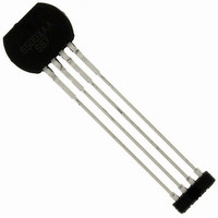
ATS667LSGTN-T Allegro Microsystems Inc, ATS667LSGTN-T Datasheet - Page 3

ATS667LSGTN-T
Manufacturer Part Number
ATS667LSGTN-T
Description
3-WIRE TRUE 0-SPEED HI ACCURACY GTS
Manufacturer
Allegro Microsystems Inc
Type
Special Purposer
Datasheet
1.ATS667LSGTN-T.pdf
(14 pages)
Specifications of ATS667LSGTN-T
Sensing Range
70% of Air Gap Trip, 30% of Air Gap Release
Voltage - Supply
4 V ~ 24 V
Current - Supply
12mA
Current - Output (max)
25mA
Output Type
Digital, Open Collector
Features
Gear Tooth Type
Operating Temperature
-40°C ~ 150°C
Package / Case
4-SIP
Operating Supply Voltage (min)
4V
Operating Supply Voltage (typ)
5/9/12/15/18V
Operating Supply Voltage (max)
24V
Output Current
20mA
Package Type
SIP Module(SG)
Pin Count
4
Mounting
Through Hole
Operating Temp Range
-40C to 150C
Operating Temperature Classification
Automotive
Lead Free Status / RoHS Status
Lead free / RoHS Compliant
Lead Free Status / RoHS Status
Lead free / RoHS Compliant
Other names
620-1328-2
ATS667LSG
OPERATING CHARACTERISTICS
Continued on the next page…
Electrical Characteristics
Supply Voltage
Undervoltage Lockout (UVLO)
Reverse Supply Current
Supply Zener Clamp Voltage
Supply Zener Current
Supply Current
Power-On State Characteristics
Power-On State
Power-On Time
OUTPUT STAGE
Low Output Voltage
Output Zener Clamp Voltage
Output Current Limit
Output Leakage Current
Output Rise Time
Output Fall Time
D-to- A Converter (DAC) Characteristics
Allowable User Induced Differential
Offset
Calibration
Initial Calibration
Update Method
Operating Characteristics (with Allegro 60-0 Reference Target)
Operational Air Gap Range
Maximum Operational Air Gap Range
Relative Repeatability
Maximum Single Outward Sudden Air
Gap Change
Duty Cycle
4,5
Characteristics
9
2
3
6
8
7
True Zero-Speed, High Accuracy Gear Tooth Sensor IC
V
AG
I
B
ΔAG
Symbol
I
Valid over operating voltage and temperature ranges; unless otherwise noted
V
OUT(OFF)
OUT(LIM)
OUT(SAT)
V
DIFFEXT
AG
CAL
POS
CC(UV)
I
V
T
RCC
I
t
ZOUT
OPMAX
V
CC
PO
I
D
t
t
CC
Z
θE
r
f
Z
OP
MAX
I
Operating, T
V
I
T
Output off
Output on
Connected as in figure 6
S
I
I
V
Output = off, V
R
10% to 90%, connected as in figure 6
R
90% to 10%, connected as in figure 6
User induced differential offset
Possible reduced edge detection accuracy, duty
cycle not guaranteed
Running mode operation, bounded for
increasing AG, unlimited for decreasing AG
Repeatability and duty cycle within specification
Output switching only (no missing edges)
100 G
S
Percentage of most recent AG
instantaneous air gap increase, f < 500 Hz,
V
Measured as V
Wobble < 0.5 mm, AG
of target rotation pin 4 to pin 1
CC
OUT
OUT
A
CC
ROT
OUT
ROT
PROC(pk-pk)
PULLUP
PULLUP
= 25°C, T
= 15 mA, T
= –18 V
= 10 mA, Output = on
= 3 mA, T
= 1000 rpm (f = 1000 Hz)
< 200 rpm; V
= 12 V, T
pk-pk
= 1 kΩ, C
= 1 kΩ, C
ideal sinusoidal signal, T
> V
J
J
< T
< T
A
J
OUT
OUT
A
Test Conditions
LOE
= 25°C
< T
= 25 °C
J
J
(max)
(max), continuous, V
L
L
CC
= 24 V
, connected as in figure 6;
J
after sudden AG change
= 4.7 nF, V
= 4.7 nF, V
(max)
> V
OP
CC
< AG
(min)
pk-pk
OP
PULLUP
PULLUP
(max) , direction
, single
A
= 150°C,
= 12 V,
= 12 V,
Z
= 26.5 V
115 Northeast Cutoff
1.508.853.5000; www.allegromicro.com
Allegro MicroSystems, Inc.
Worcester, Massachusetts 01615-0036 U.S.A.
Min.
26.5
26.5
4.0
0.5
25
42
–
–
–
4
4
–
–
–
–
–
–
–
–
–
–
–
–
Continuous
Typ.
High
0.06
100
±60
3.5
0.6
45
40
47
10
–
–
7
–
–
1
–
–
–
–
7
–
1
Max.
3.95
– 10
250
2.5
3.1
24
15
12
12
70
10
52
–
–
2
–
–
2
–
6
–
–
–
edge
Unit
deg.
mm
mm
mA
mA
mA
mA
mV
mA
ms
μA
μs
μs
G
%
%
V
V
V
V
–
–
3


