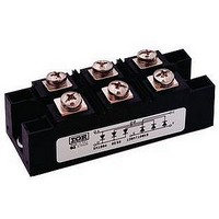
111MT80KPBF Vishay, 111MT80KPBF Datasheet

111MT80KPBF
Specifications of 111MT80KPBF
Related parts for 111MT80KPBF
111MT80KPBF Summary of contents
Page 1
THREE PHASE CONTROLLED BRIDGE Features Package fully compatible with the industry standard INT-A-pak power modules series High thermal conductivity package, electrically insulated case Outstanding number of power encapsulated components Excellent power volume ratio 4000 V isolating voltage RMS UL E78996 ...
Page 2
Series Bulletin I27503 08/97 ELECTRICAL SPECIFICATIONS Voltage Ratings Voltage V RRM Type number Code repetitive peak reverse voltage 80 100 53/52/51MT..KB 120 140 160 80 93/92/91MT..KB 100 113/112/111MT..KB 120 140 160 Forward Conduction 53MT.KB 93MT.KB 113MT.KB Parameter 52MT.KB 92MT.KB ...
Page 3
Blocking 53MT.KB 93MT.KB 113MT.KB Parameter 52MT.KB 92MT.KB 112MT.KB Units Conditions 51MT.KB 91MT.KB 111MT.KB V RMS isolation voltage INS dv/dt Max. critical rate of rise of off-state voltage (*) (*) Available with dv/dt = 1000V/ms, to complete code add S90 i.e. ...
Page 4
Series Bulletin I27503 08/97 R Conduction (per Junction) (The following table shows the increment of thermal resistance R Sinusoidal conduction @ T Devices o o 180 120 90 53/52/51MT.KB 0.072 0.085 0.108 93/92/91MT.KB 0.033 0.039 0.051 113/112/111MT.KB 0.027 0.033 ...
Page 5
Outline Table (with optional barriers) Outline Table (without optional barriers) www.irf.com 53-93-113MT..KB Series Bulletin I27503 08/97 All dimensions in millimeters (inches) All dimensions in millimeters (inches) 5 ...
Page 6
Series Bulletin I27503 08/97 130 53MT..KB Series 120 120° 110 (Rect) 100 Total Output Current (A) Fig Current Ratings Characteristic 220 53MT..KB Series 200 T = 125°C J 180 160 ...
Page 7
Series 120 120° 110 (Rect) 100 Total Output Current (A) Fig Current Ratings Characteristic 300 93MT..KB Series T = 125°C 250 J 200 120° (Rect) 150 100 ...
Page 8
Series Bulletin I27503 08/97 130 113MT..KB Series 120 120° 110 (Rect) 100 Total Output Current (A) Fig Current Ratings Characteristic 350 113MT..KB Series T = 125°C 300 J 250 120° ...
Page 9
Steady State Value R = 1.07 K/W thJC R = 0.86 K/W thJC 0.70 K/W thJC (DC Operation) 0.1 0.01 0.001 0.001 0.01 Fig Thermal Impedance Z 100 Rectangular gate pulse a) Recommended load ...


