SBR30U30CT Diodes Inc, SBR30U30CT Datasheet

RECTIFIER SBR 30A 30V TO220-3

SBR30U30CT

Manufacturer Part Number
SBR30U30CT
Description
RECTIFIER SBR 30A 30V TO220-3
Manufacturer
Diodes Inc
Series
SBR®r
Datasheets

Specifications of SBR30U30CT

Voltage - Forward (vf) (max) @ If
540mV @ 30A
Current - Reverse Leakage @ Vr
1.5mA @ 30V
Current - Average Rectified (io) (per Diode)
30A
Voltage - Dc Reverse (vr) (max)
30V
Diode Type
Super Barrier
Speed
Fast Recovery =< 500ns, > 200mA (Io)
Diode Configuration
1 Pair Common Cathode
Mounting Type
Through Hole
Package / Case
TO-220-3 (Straight Leads)
Product
Switching Diodes
Peak Reverse Voltage
30 V
Forward Continuous Current
30 A
Max Surge Current
280 A
Configuration
Dual Common Cathode
Forward Voltage Drop
0.54 V
Maximum Operating Temperature
+ 150 C
Minimum Operating Temperature
- 65 C
Mounting Style
Through Hole
Lead Free Status / RoHS Status
Lead free / RoHS Compliant
Reverse Recovery Time (trr)
-
Lead Free Status / Rohs Status
Lead free / RoHS Compliant

Available stocks

Company
Part Number
Manufacturer
Quantity
Price
Part Number:
SBR30U30CT
Manufacturer:
Diodes Inc.
Quantity:
135
Part Number:
SBR30U30CT
Manufacturer:
POWER
Quantity:
25 000
Part Number:
SBR30U30CT
Manufacturer:
DIODES
Quantity:
310
Company:
Part Number:
SBR30U30CT
Quantity:
438
Features
Features
Maximum Ratings
Electrical Characteristics
Peak Repetitive Reverse Voltage
Working Peak Reverse Voltage
DC Blocking Voltage
RMS Reverse Voltage
Average Rectified Output Current @ T
Non-Repetitive Peak Forward Surge Current 8.3ms
Single Half Sine-Wave Superimposed on Rated Load
Non-Repetitive Avalanche Energy
(T
Repetitive Peak Avalanche Power
(1µs, 25ºC)
Maximum Thermal Resistance
Thermal Resistance Junction to Ambient (Note 1)
Thermal Resistance Junction to Case
Operating and Storage Temperature Range
Reverse Breakdown Voltage (Note 2)
Forward Voltage Drop (per leg)
Leakage Current (Note 2)
Single phase, half wave, 60Hz, resistive or inductive load.
For capacitive load, derate current by 20%.
Notes:
__________
SBR is a registered trademark of Diodes Incorporated.
SBR30U30 Rev. 4 - 2
J
= 25ºC, I
Ultra Low Forward Voltage Drop
Excellent High Temperature Stability
Superior Reverse Avalanche Capability
Patented Super Barrier Rectifier Technology
Soft, Fast Switching Capability
150°C Operating Junction Temperature
Plastic TO-220AB package
Lead Free Finish, RoHS Compliant (Note 3)
AS
Characteristic
= 20A, L = 8.5 mH)
1. Test Device on Heatsink (Black Aluminum, 45mm * 20mm * 12mm)
2. Short duration pulse test used to minimize self-heating effect.
3. RoHS revision 13.2.2003. High temperature solder exemption applied, see EU Directive Annex Note 7.
Characteristic
@ T
A
= 25ºC unless otherwise specified
C
= 140ºC
@ T
Symbol
A
V
= 25ºC unless otherwise specified
(BR)R
V
I
R
F
Min
30
-
-
www.diodes.com
1 of 3
Symbol
T
V
V
V
P
j
R(RMS)
R
I
R
, T
V
E
FSM
RWM
RRM
ARM
I
RM
θ JA
θ JC
O
AS
STG
Typ
0.41
0.50
0.34
0.33
40
-
Mechanical Data
Mechanical Data
Case Material: Molded Plastic, UL Flammability
Classification Rating 94V-0
Moisture Sensitivity: Level 1 per J-STD-020C
Terminals: Matte Tin Finish annealed over
Copper leadframe. Solderable per MIL-STD-202,
Method 208
Marking Information: See Page 3
Ordering Information: See Page 3
Max
0.45
0.54
0.37
100
0.5
1.5
-
-65 to +150
Value
9800
280
800
30
21
30
17
2
Unit
mA
Super Barrier Rectifier
V
V
I
I
I
I
I
V
V
R
F
F
F
F
R
R
30A SBR
30A SBR
= 15A, T
= 30A, T
= 15A, T
= 30A, T
= 1.5mA
= 30V, T
= 30V, T
Test Condition
SBR30U30CT
© Diodes Incorporated
j
j
j
j
= 25ºC
= 25ºC
= 125ºC
= 125ºC
j
j
= 25ºC
= 125ºC
January 2008
ºC/W
Unit
®
®
mJ
ºC
W
V
V
A
A

Related parts for SBR30U30CT

SBR30U30CT Summary of contents

Page 1

... STG = 25ºC unless otherwise specified A Symbol Min Typ (BR)R 0.41 0. 0.34 — 0. www.diodes.com SBR30U30CT ® ® 30A SBR 30A SBR Super Barrier Rectifier Super Barrier Rectifier Value Unit 280 800 9800 17 ºC/W 2 -65 to +150 Max Unit Test Condition - 1.5mA 15A 25º ...

Page 2

... SBR30U30 Rev 100,000 10,000 1,000 100 10 1 125 150 175 0.01 Fig. 4 Maximum Avalanche Power Curve, Per Element θ θ 125 150 175 www.diodes.com SBR30U30CT 0 100 1,000 T , PULSE DURATION (uS AVERAGE FORWARD CURRENT (A) F(AV) Fig. 6 Forward Power Dissipation January 2008 © Diodes Incorporated 20 ...
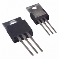
Page 3

... All Dimensions in Millimeters CASE Polarity Case t Common Cathode Anode Anode Date Code YY = Last two digits of year 2007 WW = Week (01-52) IMPORTANT NOTICE LIFE SUPPORT www.diodes.com SBR30U30CT MAX. 4.67 0.91 1.37 0.53 15.35 8.90 10.31 5.18 1.37 2.82 13.80 3.96 3.935 2.89 Marking Weight 2 ...

Related keywords