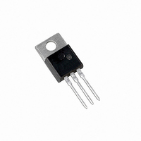
MBR30H30CTG ON Semiconductor, MBR30H30CTG Datasheet

MBR30H30CTG
Specifications of MBR30H30CTG
Available stocks
Related parts for MBR30H30CTG
MBR30H30CTG Summary of contents
Page 1
... CASE 221A PLASTIC Assembly Location Y = Year WW = Work Week B30H30 = Device Code G = Pb-Free Package AKA = Diode Polarity ORDERING INFORMATION Device Package MBRB30H30CT-1G TO-262 (Pb-Free) MBR30H30CTG TO-220 (Pb-Free MARKING DIAGRAM AYWW B30H30G AKA AYWW B30H30G AKA Shipping 50 Units/Rail 50 Units/Rail Publication Order Number: MBRB30H30CT-1/D ...
Page 2
... MAXIMUM RATINGS Please See the Table on the Following Page *For additional information on our Pb-Free strategy and soldering details, please download the ON Semiconductor Soldering and Mounting Techniques Reference Manual, SOLDERRM/D. MBRB30H30CT-1G, MBR30H30CTG http://onsemi.com 2 ...
Page 3
... Recommended Operating Conditions is not implied. Extended exposure to stresses above the Recommended Operating Conditions may affect device reliability. 1. The heat generated must be less than the thermal conductivity from Junction-to-Ambient Pulse Test: Pulse Width = 300 ms, Duty Cycle ≤ 2.0%. MBRB30H30CT-1G, MBR30H30CTG Rating (Per Diode Leg) http://onsemi.com ...
Page 4
... MBRB30H30CT-1G, MBR30H30CTG 100 T = 125° 25° 0.1 0 0.1 0.2 0.3 0.4 0.5 0 INSTANTANEOUS FORWARD VOLTAGE (VOLTS) F Figure 1. Typical Forward Voltage 1.0E-00 1.0E- 125°C J 1.0E-02 1.0E- 25°C J 1.0E-04 1.0E- REVERSE VOLTAGE (VOLTS) R Figure 3. Typical Reverse Current SQUARE WAVE 100 110 120 ...
Page 5
... MBRB30H30CT-1G, MBR30H30CTG 3000 2500 2000 1500 1000 500 0 0 Figure 7. Typical Capacitance for MBR30H30CTG 0.5 1 0.2 0.1 0.05 0.1 0.01 SINGLE PULSE 0.01 0.000001 0.00001 0.0001 Figure 8. Thermal Response Junction-to-Case T = 25° REVERSE VOLTAGE (VOLTS) R 0.001 0.01 0 TIME (sec) 1 http://onsemi.com ...
Page 6
... DD breakdown (from minus any losses due to finite 1 2 component resistances. Assuming the component resistive MBRB30H30CT-1G, MBR30H30CTG elements are small Equation (1) approximates the total energy transferred to the diode. It can be seen from this equation that if the V breakdown voltage of the device, the amount of energy ...
Page 7
... MBRB30H30CT-1G, MBR30H30CTG - -T- SEATING K PLANE 0.13 (0.005 PACKAGE DIMENSIONS 2 I PAK (TO-262) CASE 418D-01 ISSUE NOTES: 1. DIMENSIONING AND TOLERANCING PER ANSI Y14.5M, 1982. 2. CONTROLLING DIMENSION: INCH http://onsemi.com 7 INCHES MILLIMETERS DIM MIN MAX MIN MAX A 0.335 0.380 8.51 9.65 B 0.380 0.406 9.65 10 ...
Page 8
... MBRB30H30CT-1G, MBR30H30CTG SWITCHMODE is a trademark of Semiconductor Components Industries, LLC. ON Semiconductor and are registered trademarks of Semiconductor Components Industries, LLC (SCILLC). SCILLC reserves the right to make changes without further notice to any products herein. SCILLC makes no warranty, representation or guarantee regarding the suitability of its products for any particular purpose, nor does SCILLC assume any liability arising out of the application or use of any product or circuit, and specifically disclaims any and all liability, including without limitation special, consequential or incidental damages. “ ...


