20CJQ100 Vishay, 20CJQ100 Datasheet

DIODE SCHOTTKY 100V 1A SOT-223

20CJQ100

Manufacturer Part Number
20CJQ100
Description
DIODE SCHOTTKY 100V 1A SOT-223
Manufacturer
Vishay
Datasheets

Specifications of 20CJQ100

Diode Configuration
1 Pair Common Cathode
Diode Type
Schottky
Voltage - Forward (vf) (max) @ If
790mV @ 1A
Current - Reverse Leakage @ Vr
100µA @ 1000V
Current - Average Rectified (io) (per Diode)
1A
Voltage - Dc Reverse (vr) (max)
100V
Speed
Fast Recovery =< 500ns, > 200mA (Io)
Mounting Type
Surface Mount
Package / Case
SOT-223 (3 leads + Tab), SC-73, TO-261
Product
Schottky Rectifiers
Peak Reverse Voltage
100 V
Forward Continuous Current
4 A
Max Surge Current
380 A
Configuration
Dual Common Cathode
Forward Voltage Drop
0.89 V at 2 A
Maximum Reverse Leakage Current
100 uA
Operating Temperature Range
- 55 C to + 175 C
Mounting Style
SMD/SMT
Repetitive Reverse Voltage Vrrm Max
100V
Forward Current If(av)
2A
Forward Voltage Vf Max
890mV
Lead Free Status / RoHS Status
Contains lead / RoHS non-compliant
Reverse Recovery Time (trr)
-
Lead Free Status / RoHS Status
Contains lead / RoHS non-compliant, Contains lead / RoHS non-compliant
Other names
*20CJQ100
VS-20CJQ100
VS-20CJQ100
VS20CJQ100
VS20CJQ100

Available stocks

Company
Part Number
Manufacturer
Quantity
Price
Part Number:
20CJQ100PBF
Manufacturer:
VISHAY
Quantity:
5 600
Part Number:
20CJQ100TRPBF
Manufacturer:
FREESCALE
Quantity:
2 100
Document Number: 93274
Revision: 22-Aug-08
PRODUCT SUMMARY
MAJOR RATINGS AND CHARACTERISTICS
SYMBOL
I
V
I
V
T
VOLTAGE RATINGS
PARAMETER
DC reverse voltage
Working peak reverse voltage
ABSOLUTE MAXIMUM RATINGS
PARAMETER
Maximum average
forward current
See fig. 5
Maximum peak one cycle
non-repetitive surge current per leg
See fig. 7
Non-repetitive avalanche energy per leg
Repetitive avalanche current per leg
F(AV)
FSM
RRM
F
J
SOT-223
I
F(AV)
V
R
per device
Rectangular waveform
t
1 Apk, T
Range
Anode
p
= 5 µs sine
per leg
1
J
For technical questions, contact: diodes-tech@vishay.com
Common
common
cathode
Schottky Rectifier, 2 x 1 A
CHARACTERISTICS
= 125 °C (per leg)
Base
SYMBOL
2 x 1 A
2
100 V
4
I
I
F(AV)
E
FSM
I
AR
AS
3
Anode
SYMBOL
50 % duty cycle at T
5 µs sine or 3 µs rect. pulse
10 ms sine or 6 ms rect. pulse
T
Current decaying linearly to zero in 1 µs
Frequency limited by T
V
J
V
RWM
= 25 °C, I
R
AS
= 1 A, L = 2 mH
FEATURES
• Small foot print, surface mountable
• Low profile
• Very low forward voltage drop
• High frequency operation
• Guard ring for enhanced ruggedness and long term
• Common cathode
• Designed and qualified for industrial level
DESCRIPTION
The 20CJQ100 surface mount Schottky rectifier series has
been designed for applications requiring very low forward
drop and very small foot prints. Typical applications are in
portables, switching power supplies, converters, automotive
system, freewheeling diodes, battery charging, and reverse
battery protection.
TEST CONDITIONS
reliability
C
= 129 °C, rectangular waveform
J
maximum V
20CJQ100
Following any rated
load condition and with
rated V
- 55 to 175
Vishay High Power Products
VALUES
A
0.67
100
100
380
= 1.5 x V
2
RRM
applied
R
typical
VALUES
20CJQ100
380
22
1
2
1
1
UNITS
UNITS
www.vishay.com
°C
V
A
V
A
V
UNITS
mJ
A
A
1

Related parts for 20CJQ100

20CJQ100 Summary of contents

Page 1

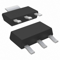
... Anode • Common cathode 3 • Designed and qualified for industrial level DESCRIPTION The 20CJQ100 surface mount Schottky rectifier series has been designed for applications requiring very low forward drop and very small foot prints. Typical applications are in 100 V portables, switching power supplies, converters, automotive system, freewheeling diodes, battery charging, and reverse battery protection ...

Page 2

... Vishay High Power Products ELECTRICAL SPECIFICATIONS PARAMETER Maximum forward voltage drop per leg See fig. 1 Maximum reverse leakage current per leg See fig. 2 Typical junction capacitance per leg Typical series inductance per leg Maximum voltage rate of change Note (1) Pulse width < 300 µs, duty cycle < ...

Page 3

... V - Reverse Voltage (V) R Fig Typical Junction Capacitance vs. Reverse Voltage 0.20 0.001 0. Rectangular Pulse Duration (s) 1 Fig Maximum Thermal Impedance Z For technical questions, contact: diodes-tech@vishay.com 20CJQ100 Vishay High Power Products 175 ° 150 ° 125 ° 100 ° ° ...

Page 4

... Vishay High Power Products 200 180 160 140 Square wave (D = 0.50) 120 80 % rated V applied R 100 80 See note ( 0.5 1.0 1 Average Forward Current (A) F(AV) Fig Maximum Allowable Case Temperature vs. Average Forward Current Current monitor Note (1) Formula used ( REV Pd = Forward power loss = I ...

Page 5

... Circuit configuration Common cathode - Package SOT-223 - Schottky “Q” series - Voltage rating (100 = 100 V) - None = Standard production PbF = Lead (Pb)-free LINKS TO RELATED DOCUMENTS For technical questions, contact: diodes-tech@vishay.com 20CJQ100 Vishay High Power Products 100 - 6 7 http://www.vishay.com/doc?95022 http://www.vishay.com/doc?95031 http://www.vishay.com/doc?95035 www.vishay.com 5 ...

Page 6

... Vishay disclaims any and all liability arising out of the use or application of any product described herein or of any information provided herein to the maximum extent permitted by law. The product specifications do not expand or otherwise modify Vishay’ ...

Related keywords