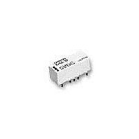
G6ZU-1P-A DC24 Omron, G6ZU-1P-A DC24 Datasheet - Page 15

G6ZU-1P-A DC24
Manufacturer Part Number
G6ZU-1P-A DC24
Description
Latching HF TH 50 Relay
Manufacturer
Omron
Series
G6Zr
Datasheet
1.G6Z-1PE_DC5.pdf
(16 pages)
Specifications of G6ZU-1P-A DC24
Relay Type
RF
Circuit
SPDT (1 Form C)
Contact Rating @ Voltage
0.01A @ 30VAC/DC
Coil Type
Latching, Single Coil
Coil Current
8.3mA
Coil Voltage
24VDC
Control On Voltage (max)
18 VDC
Mounting Type
Through Hole
Termination Style
PC Pin
Contact Form
1 Form C
Power Consumption
200 mW
Isolation
60 dB to 65 dB at 900 MHz / 30 dB to 45 dB at 2.6 GHz
Insertion Loss
0.1 dB to 0.2 dB at 900 MHz / 0.3 dB to 0.5 dB at 2.6 GHz
Lead Free Status / RoHS Status
Lead free / RoHS Compliant
Control Off Voltage (min)
-
Lead Free Status / Rohs Status
Lead free / RoHS Compliant
Other names
G6ZU-1P-ADC24
G6ZU1PADC24
G6ZU1PADC24
Claw Securing Force During Automatic Mounting
During automatic insertion of Relays, be sure to set the securing
force of each claw to the following so that the Relay’s characteristics
will be maintained.
Latching Relay Mounting
Make sure that the vibration or shock that is generated from other
devices, such as Relays, on the same panel or substrate and
imposed on the Latching Relay does not exceed the rated value, oth-
erwise the set/reset status of the Latching Relay may be changed.
The Latching Relay is reset before shipping. If excessive vibration or
shock is imposed, however, the Latching Relay may be set acciden-
tally. Be sure to apply a reset signal before use.
Coating
Do not use silicone coating to coat the Relay when it is mounted to
the PCB. Do not wash the PCB after the Relay is mounted using
detergent containing silicone. Otherwise, the detergent may remain
on the surface of the Relay.
Secure the claws to the shaded area.
Do not attach them to the center area
or to only part of the Relay.
B
Direction A: 4.90 N max.
Direction B: 4.90 N max.
Direction C: 4.90 N max.
High-frequency Relay
G6Z
355


