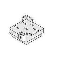
P7M-06P Omron, P7M-06P Datasheet - Page 3

P7M-06P
Manufacturer Part Number
P7M-06P
Description
MKS-X PCB Socket
Manufacturer
Omron
Series
P7Mr
Datasheet
1.MKS1XT-10_DC24.pdf
(12 pages)
Specifications of P7M-06P
Accessory Type
Socket, Back Connecting
Associated Relay Series
MKS-X
Mounting Style
PCB
Lead Free Status / Rohs Status
Lead free / RoHS Compliant
■ Coil Ratings
Note: 1. The rated current and coil resistance are measured at a coil temperature of 23°C with tolerances of +15%/-20% for AC rated current and
■ Characteristics
Note: 1. The values given above are initial values.
Rated voltage (V)
AC
DC
Contact resistance (See note 2)
Operate time (See note 3)
Release time (See note 3)
Max. operating frequency Mechanical
Insulation resistance (See note 4)
Dielectric strength
Vibration resistance
Shock resistance
Life expectancy
Minimum permissible load
(Reference value. See note 6)
Ambient operating temperature
Ambient operating humidity
Weight
2. Performance characteristic data are measured at a coil temperature of 23°C.
3. The Maximum Voltage is the highest voltage that can be applied to the coil temporarily, not continuously.
4. The rated current is approximately 5 mA higher for Models with Built-in Operation Indicators (DC operating coils).
2. The contact resistance was measured for 1 A at 5 VDC using the voltage drop method.
3. The operate time was measured with the rated voltage imposed and any contact bounce ignored at an ambient temperature of 23°C.
4. The insulation resistance was measured with a 500-VDC insulation resistance tester at the same places as those used for checking the
5. The electrical endurance was measured at an ambient temperature of 23°C.
6. P level: λ
24
100
110
120
200
220
230
240
12
24
48
110
220
±15% for DC coil resistance.
dielectric strength.
Item Rated current (mA)
60
=0.1 x 10
110
26.6
24.2
22.2
13.3
12.1
11.5
11.0
126
63.2
32.0
13.6
6.8
50 Hz
Electrical
Mechanical
Electrical (See note 5) 100,000 operations min. (at rated load and maximum switching frequency)
-6
/operations
96.3
23.1
21.0
19.3
11.6
10.5
10.0
9.6
60 Hz
48.4
760
932
1,130
3,160
3,550
4,250
4,480
95
380
1,500
8,060
32,200
Coil resistance
(Ω)
100 mΩ max.
AC: 20 ms max.
DC: 30 ms max.
20 ms max.
18,000 operations/h
Models for DC loads: 1,800 times/hour
Models for AC loads: 1,200 times/hour
100 MΩ min.
2,500 VAC 50/60 Hz for 1 min. between coil and contacts
2,500 VAC 50/60 Hz for 1 min. between contacts of different polarity
1,000 VAC 50/60 Hz for 1 min. between contacts of same polarity
Destruction:
Malfunction:
Destruction:
Malfunction
1,000,000 operations min. (at 18,000 operations/hr)
10 mA at 24 VDC
−40°C to 60°C (with no icing or condensation)
Note: The range is −25°C to 60°C for models with built-in operation indicators.
5% to 85%
SPST-NO: Approx. 73 g, SPST-NO/SPST-NC: Approx. 82 g
80% max. of rated
voltage
Must operate
voltage (V)
10 to 55 Hz, 1.0-mm double amplitude
10 to 55 Hz, 1.5-mm double amplitude
1,000 m/s
500m/s
100 m/s
General Purpose Power Relays
2
2
when relay is properly mounted into P7MF-06(-D) socket
30% min. of rated
voltage at 60 Hz
25% min. of rated
voltage at 50 Hz
15% min. of rated
voltage
2
when relay is properly mounted into P7M-06P PCB socket
Must release
voltage (V)
110% of rated
voltage
Max. voltage (V)
MKS-X
Approx. 2.3 VA
at 60 Hz
Approx. 2.7 VA
at 50 Hz
Approx. 1.5 W
Power consumption
(VA, W)
3


