DSAI35-16A IXYS, DSAI35-16A Datasheet
DSAI35-16A
Manufacturer Part Number
DSAI35-16A
Description
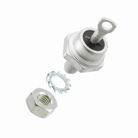
DIODE CATH 1600V 49A DO-203AB
Manufacturer
IXYS
Datasheet
1.DSAI35-16A.pdf
(2 pages)
Specifications of DSAI35-16A
Voltage - Forward (vf) (max) @ If
1.55V @ 150A
Voltage - Dc Reverse (vr) (max)
1600V (1.6kV)
Current - Average Rectified (io)
49A
Current - Reverse Leakage @ Vr
4mA @ 1600V
Diode Type
Avalanche
Speed
Standard Recovery >500ns, > 200mA (Io)
Mounting Type
Chassis, Stud Mount
Package / Case
DO-203AB, DO-5, Stud
Product
Standard Recovery Rectifier
Configuration
Single
Reverse Voltage
1600 V
Forward Voltage Drop
1.55 V at 150 A
Forward Continuous Current
49 A
Max Surge Current
650 A
Reverse Current Ir
4000 uA
Mounting Style
Through Hole
Maximum Operating Temperature
+ 180 C
Minimum Operating Temperature
- 40 C
Vrrm, (v)
1600
Ifavm, Total, (a)
49
Ifavm, Per Diode, (a)
49
@ Tc, (°c)
100
Prsm, (kw)
11
Ifrms, (a)
80
Ifsm, 10 Ms, Tvj = 45°c, (a)
650
Vt0, (v)
0.85
Rt, (mohms)
4.5
Tvjm, (°c)
180
Rthjc, Max, (k/w)
1.05
Rthch, (k/w)
1.25
Package Style
DO-203AB (DO-5)
Lead Free Status / RoHS Status
Lead free / RoHS Compliant
Reverse Recovery Time (trr)
-
Capacitance @ Vr, F
-
Lead Free Status / Rohs Status
Details


Rectifier Diode
Avalanche Diode
V
Symbol
I
I
P
I
I
T
T
T
M
Weight
Symbol
I
V
V
r
R
R
d
d
a
Data according to IEC 60747
IXYS reserves the right to change limits, test conditions and dimensions
© 2000 IXYS All rights reserved
1300
1300
1700
1900
F(RMS)
F(AVM)
FSM
2
R
T
t
VJ
VJM
stg
S
A
RSM
RSM
F
T0
thJC
thJH
V
900
d
Only for Avalanche Diodes
V
1300
1750
1950
(BR)min
V
-
-
Test Conditions
T
T
DSA(I) types, T
T
V
T
V
T
V
T
V
Mounting torque
Test Conditions
T
I
For power-loss calculations only
T
DC current
DC current
Creepage distance on surface
Strike distance through air
Max. allowable acceleration
F
VJ
case
VJ
VJ
VJ
VJ
VJ
VJ
R
R
R
R
ÿ
= T
= 100°C; 180° sine
= 45°C;
= 0
= T
= 0
= 45°C
= 0
= T
= 0
= T
= 150 A; T
= T
1200
1200
1600
1800
V
V
800
VJM
VJM
VJM
VJM
VJM
RRM
; V
R
= V
VJ
VJ
DS 35-08A
DS 35-12A
DSA 35-12A
DSA 35-16A
DSA 35-18A
= T
t = 10 ms (50 Hz), sine
t = 8.3 ms (60 Hz), sine
t = 10 ms (50 Hz), sine
t = 8.3 ms (60 Hz), sine
t = 10 ms (50 Hz), sine
t = 8.3 ms (60 Hz), sine
t = 10 ms (50 Hz), sine
t = 8.3 ms (60 Hz), sine
= 25°C
RRM
Anode
on stud
VJM
, t
p
= 10 ms
DSI 35-08A
DSI 35-12A
DSAI 35-12A
DSAI 35-16A
DSAI 35-18A
Cathode
on stud
Characteristic Values
-40...+180
-40...+180
Maximum Ratings
£
£
4.5-5.5
40-49
2100
2000
1800
1700
1.55
0.85
1.05
1.25
4.05
650
690
600
640
180
100
4.5
3.9
80
49
11
15
4
lb.in.
K/W
K/W
m/s
mm
mm
A
Nm
mW
kW
A
A
A
mA
°C
°C
°C
A
A
A
A
A
A
V
V
g
2
2
2
2
s
s
s
s
2
V
I
I
DO-203 AB
C
A
A = Anode
Features
Applications
Advantages
Dimensions in mm (1 mm = 0.0394")
F(RMS)
F(AV)M
International standard package,
JEDEC DO-203 AB (DO-5)
Planar glassivated chips
High power rectifiers
Field supply for DC motors
Power supplies
Space and weight savings
Simple mounting
Improved temperature and power
cycling
Reduced protection circuits
RRM
DS 35
DSA 35
DS
DSA
= 800-1800 V
= 80 A
= 49 A
C = Cathode
1/4-28UNF
DSI 35
DSAI 35
A
C
DSI
DSAI
1 - 2
Related parts for DSAI35-16A
Image
Part Number
Description
Manufacturer
Datasheet
Request
R

Part Number:
Description:
DIODE CATH 1200V 49A DO-203AB
Manufacturer:
IXYS
Datasheet:
Part Number:
Description:
DIODE CATH 1800V 49A DO-203AB
Manufacturer:
IXYS
Datasheet:

Part Number:
Description:
HiPerFET Power MOSFETs
Manufacturer:
IXYS Corporation
Datasheet:
Part Number:
Description:
J-K-Type Flip-Flop
Manufacturer:
IXYS Corporation
Datasheet:
Part Number:
Description:
HiPerRF Power MOSFETs
Manufacturer:
IXYS Corporation
Datasheet:
Part Number:
Description:
Rectifier Module for Three Phase Power Factor Correction
Manufacturer:
IXYS Corporation
Datasheet:
Part Number:
Description:
Thyristor Modules Thyristor/Diode Modules
Manufacturer:
IXYS Corporation
Datasheet:
Part Number:
Description:
Thyristor Modules Thyristor/Diode Modules
Manufacturer:
IXYS Corporation
Datasheet:
Part Number:
Description:
Thyristor Modules Thyristor/Diode Modules
Manufacturer:
IXYS Corporation
Datasheet:
Part Number:
Description:
Thyristor Modules Thyristor/Diode Modules
Manufacturer:
IXYS Corporation
Datasheet:
Part Number:
Description:
Thyristor Modules /Diode Modules
Manufacturer:
IXYS Corporation
Datasheet:
DSAI35-16A Summary of contents
Page 1
... Creepage distance on surface S d Strike distance through air A a Max. allowable acceleration Data according to IEC 60747 IXYS reserves the right to change limits, test conditions and dimensions © 2000 IXYS All rights reserved Cathode on stud DSI 35-08A DSI 35-12A DSAI 35-12A DSAI 35-16A ...
Page 2
... Fig. 4 Power dissipation versus forward current and ambient temperature 2.0 K/W 1.6 Z thJH 1.2 0.8 0.4 0 Fig. 6 Transient thermal impedance junction to heatsink © 2000 IXYS All rights reserved 1000 50Hz, 80% V RRM A 900 800 700 I FSM 600 T = 45°C VJ 500 400 T = 180° ...