A22EL-M-24A-02 Omron, A22EL-M-24A-02 Datasheet - Page 15
A22EL-M-24A-02
Manufacturer Part Number
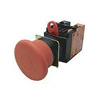
A22EL-M-24A-02
Description
IL ESTOP 40mm 24V DPST-NC
Manufacturer
Omron
Series
A22r
Type
Emergency Stop, Illuminatedr
Specifications of A22EL-M-24A-02
Illumination Color
Red
Circuit
DPST-NC
Switch Function
On-Off
Contact Rating @ Voltage
10A @ 110VAC
Actuator Type
Mushroom Button
Illumination Type, Color
LED, Red
Illumination Voltage (nominal)
24 VAC/DC
Mounting Type
Panel Mount
Termination Style
Screw Terminal
Contact Form
DPST - NC
Contact Rating
10 Amps at 110 Volts
Actuator
Round, Medium
Mounting Style
Through Hole
Illumination
Illuminated
Body Shape
Square
Dielectric Strength
2500 Volts
Features
Easy mounting and removal of switch unit
Insulation Resistance
100 MOhms
Mounting Angle
Straight
Water / Moisture Rating
IP65
Contact Configuration
DPST-NC
Switch Operation
Pushlock Turn Reset
Contact Voltage Ac Nom
440V
Contact Voltage Dc Nom
380V
Contact Current Max
24A
Lead Free Status / RoHS Status
Lead free / RoHS Compliant
Lead Free Status / RoHS Status
Lead free / RoHS Compliant
Other names
A22ELM24A02


Assembling the Cap
Installing/Replacing the Lamp
Control Box (Enclosure)
• Insert the protrusion of the Tightening Wrench (A22Z-3905) into the Cap slot and then turn to remove the Cap.
• Insert the Lamp Extractor (A22Z-3901) into the lamp, then rotate the Extractor
The Standard-size Legend Plate Frame can
be mounted.
Mount the Frame as shown in the following
diagram. Mount the Switch in the same way
as for an ordinary panel.
while pressing it.
(1) Mounting the Switch
(1) Installing/Replacing from the Panel Surface
Snap-in Legend Plate
Cap slot Protrusion
Emergency Stop Switch
Place the tip of a screwdriver on the surface
where the cable port hole is to be created
with the cover attached and strike the
screwdriver to punch a hole.
Attempts to punch a hole on the other side
of the case will damage the Box.
(2) Creating a Cable Port Hole
• Grip the indicator with your fingers, then rotate the indicator while pressing it
against the Switch.
1. Insert the connector into the cable port hole in the Box and secure
2. Pass the tightening cap through the cable, insert the cable into the
with the Mounting Ring inside the box.
connector, and tighten the tightening cap to secure the cable.
Mounting
RIng
Inside
Box
(2) Installing/Replacing on the Switch
(3) Securing the Connector Cable
Outside
Rubber washer
Connector
7 to 9 dia.
9 to 11 dia.
Cable diameter
Tightening cap
A22Z-3500-1
A22Z-3500-2
Connector
A22E
Cable
15
Related parts for A22EL-M-24A-02
Image
Part Number
Description
Manufacturer
Datasheet
Request
R

Part Number:
Description:
Lighted,pushlock,turnreset,1NC
Manufacturer:
Omron
Datasheet:

Part Number:
Description:
Lighted,pushlock,turnreset,1NC
Manufacturer:
Omron
Datasheet:

Part Number:
Description:
IL ESTOP OP UNIT 40mm P-L,T-R
Manufacturer:
Omron
Datasheet:
Part Number:
Description:
Lighted,pushlock,turnreset,1NC
Manufacturer:
Omron
Datasheet:
Part Number:
Description:
Lighted,pushlock,turnreset,2NC
Manufacturer:
Omron
Datasheet:
Part Number:
Description:
Lighted,pushlock,turnreset,1NC
Manufacturer:
Omron
Datasheet:

Part Number:
Description:
Lighted,pushlock,turnreset,1NC
Manufacturer:
Omron
Datasheet:
Part Number:
Description:
Lighted,pushlock,turnreset,2NC
Manufacturer:
Omron
Datasheet:

Part Number:
Description:
Lighted,pushlock,turnreset,1NC
Manufacturer:
Omron
Datasheet:
Part Number:
Description:
SWITCH PB RND MOM SPST-NO/NC RED
Manufacturer:
Omron
Datasheet:

Part Number:
Description:
SWITCH PB ROUND ALT SPST-NO BLUE
Manufacturer:
Omron
Datasheet:

Part Number:
Description:
SWITCH PB ROUND ALT SPST-NO BLK
Manufacturer:
Omron
Datasheet:

Part Number:
Description:
SWITCH PB ROUND ALT SPST-NO GRN
Manufacturer:
Omron
Datasheet:

Part Number:
Description:
SWITCH PB ROUND ALT SPST-NO RED
Manufacturer:
Omron
Datasheet: