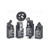
D4N-2120 Omron, D4N-2120 Datasheet - Page 18

D4N-2120
Manufacturer Part Number
D4N-2120
Description
PlasLS/Jap/Snp1NC1NO/RlrLvr
Manufacturer
Omron
Series
D4Nr
Datasheet
1.D4N-2120.pdf
(24 pages)
Specifications of D4N-2120
Contact Form
NO / NC
Contact Rating
3 Amps
Actuator
Lever, Roller
Operating Force
5 N
Termination Style
Screw
Circuit
DPST (1-NO, 1-NC)
Switch Function
On-Mom, Off-Mom
Contact Rating @ Voltage
10A @ 120VAC
Actuator Type
Lever, Roller
Mounting Type
Chassis Mount
Lead Free Status / RoHS Status
Lead free / RoHS Compliant
Lead Free Status / RoHS Status
Lead free / RoHS Compliant
Safety Precautions
Refer to the “Precautions for All Switches” and “Precautions for All Safety Limit Switches”.
The Switch contacts can be used with either standard loads or
microloads. Once the contacts have been used to switch a load,
however, they cannot be used to switch smaller loads. The contact
surfaces will become rough once they have been used and contact
reliability for smaller loads may be reduced.
Mounting Method
Appropriate Tightening Torque
Tighten each of the screws to the specified torque. Loose screws may
result in malfunction of the Switch within a short time.
Electric shock may occasionally occur.
Do not use metal connectors or metal conduits.
• Do not use the Switch submerged in oil or water, or in locations
• Always attach the cover after completing wiring and before using
• Do not switch circuits for two or more standard loads (250 VAC,
1
2
3
4
5
6
7
continuously subject to splashes of oil or water. Doing so may
result in oil or water entering the Switch interior. (The IP67 degree
of protection specification for the Switch refers to water penetration
while the Switch is submersed in water for a specified period of
time.)
the Switch. Also, do not turn ON the Switch with the cover open.
Doing so may result in electric shock.
3 A). Doing so may adversely affect insulation performance.
2
Terminal screw
Cover mounting screw
Head mounting screw
Lever mounting screw
Body mounting screw
Connector, M12 adaptor
Cap screw
4
5
1
Precautions for Correct Use
Precautions for Safe Use
!CAUTION
3
6
0.6 to 0.8 N·m
0.5 to 0.7 N·m
0.5 to 0.6 N·m
1.6 to 1.8 N·m
0.5 to 0.7 N·m
1.8 to 2.2 N·m (except 1/2-14NPT)
1.4 to 1.8 N·m (for 1/2-14NPT)
1.3 to 1.7 N·m
7
Switch Mounting
Switch Mounting Holes
• Mount the Switch using M4 screws and spring washers and tighten
• For safety, use screws that cannot be easily removed, or use an
• As shown below, two studs with a maximum height of 4.8 mm and
• Make sure that the dog contacts the actuator at a right angle.
2.5
47
±0.1
the screws to the specified torque.
equivalent measure to ensure that the Switch is secure.
a diameter of 4
holes on the bottom of the Switch, and the Switch secured at four
locations to increase the mounting strength.
Applying a load to the switch actuator (roller) on a slant may result
in deformation or damage of the actuator or rotary shaft.
±0.1
One-conduit Type
Two, M4
20
22
22
±0.1
±0.1
±0.1
4
Height: 4.8 max.
−0.05
−0.15
−0.05
−0.15
dia.
Incorrect
mm can be provided, the studs inserted into the
5.35
±0.1
2.5
39
Dog
±0.1
±0.1
Correct
Two-conduit Type
Two, M4
20
22
40
42
42
±0.1
±0.1
±0.1
±0.1
±0.1
4
Height: 4.8 max.
−0.05
−0.15
dia.
D4N
18


