60EPU06 Vishay, 60EPU06 Datasheet
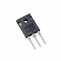
DIODE 600V 60A FAST TO-247AC

60EPU06

Manufacturer Part Number
60EPU06
Description
DIODE 600V 60A FAST TO-247AC
Manufacturer
Vishay
Series
FRED Pt™r
Datasheet

Specifications of 60EPU06

Voltage - Forward (vf) (max) @ If
1.68V @ 60A
Voltage - Dc Reverse (vr) (max)
600V
Current - Average Rectified (io)
60A
Current - Reverse Leakage @ Vr
50µA @ 600V
Diode Type
Standard
Speed
Fast Recovery =< 500ns, > 200mA (Io)
Reverse Recovery Time (trr)
81ns
Mounting Type
Through Hole, Radial
Package / Case
TO-247-2 (TO-247AC Modified)
Product
Ultra Fast Recovery Rectifier
Configuration
Single
Reverse Voltage
600 V
Forward Voltage Drop
1.68 V
Recovery Time
45 ns
Forward Continuous Current
60 A
Max Surge Current
600 A
Reverse Current Ir
50 uA
Mounting Style
Through Hole
Maximum Operating Temperature
+ 175 C
Minimum Operating Temperature
- 55 C
Lead Free Status / RoHS Status
Contains lead / RoHS non-compliant
Capacitance @ Vr, F
-
Lead Free Status / Rohs Status
No RoHS Version Available
Other names
*60EPU06
VS-60EPU06
VS-60EPU06
VS60EPU06
VS60EPU06

Available stocks

Company
Part Number
Manufacturer
Quantity
Price
Part Number:
60EPU06PBF
Manufacturer:
IXYS
Quantity:
6 000
Company:
Part Number:
60EPU06PBF
Quantity:
70 000
Company:
Part Number:
60EPU06PBF
Quantity:
70 000
Document Number: 93021
Revision: 02-Jun-08
PRODUCT SUMMARY
ABSOLUTE MAXIMUM RATINGS
PARAMETER
Cathode to anode voltage
Continuous forward current
Single pulse forward current
Maximum repetitive forward current
Operating junction and storage temperatures
ELECTRICAL SPECIFICATIONS (T
PARAMETER
Breakdown voltage,
blocking voltage
Forward voltage
Reverse leakage current
Junction capacitance
TO-247AC (modified)
Cathode
t
rr
(typical)
I
F(AV)
60EPU06
V
1
Cathode
R
to base
2
Anode
3
SYMBOL
V
C
V
V
I
BR
R
F
T
r
Anode
,
Ultrafast Soft Recovery Diode,
TO-247AC
For technical questions, contact: diodes-tech@vishay.com
60APU06
1
Cathode
to base
I
I
I
I
V
T
V
R
F
F
F
J
R
R
= 60 A
= 60 A, T
= 60 A, T
600 V
= 100 µA
34 ns
= 150 °C, V
60 A
= V
= 600 V
2
Anode
R
J
rated
60 A FRED Pt
3
= 25 °C unless otherwise specified)
SYMBOL
J
J
T
I
= 125 °C
= 175 °C
J
I
I
F(AV)
TEST CONDITIONS
FSM
FRM
, T
V
R
R
= V
Stg
R
rated
T
T
Square wave, 20 kHz
C
C
TEST CONDITIONS
= 116 °C
= 25 °C
FEATURES
• Ultrafast recovery
• 175 °C operating junction temperature
• Designed and qualified for industrial level
BENEFITS
• Reduced RFI and EMI
• Higher frequency operation
• Reduced snubbing
• Reduced parts count
DESCRIPTION/APPLICATIONS
These diodes are optimized to reduce losses and EMI/RFI
in high frequency power conditioning systems.
The softness of the recovery eliminates the need for a
snubber in most applications. These devices are ideally
suited for HF welding, power converters and other
applications where switching losses are not significant
portion of the total losses.
TM
Vishay High Power Products
MIN.
600
-
-
-
-
-
-
60EPU06/60APU06
- 55 to 175
MAX.
600
600
120
60
TYP.
1.35
1.20
1.11
39
-
-
-
MAX.
1.68
1.42
1.30
500
50
-
-
www.vishay.com
UNITS
°C
V
A
UNITS
µA
pF
V
1

Related parts for 60EPU06

60EPU06 Summary of contents

Page 1

... 125 ° 175 ° rated 150 ° rated 600 V R For technical questions, contact: diodes-tech@vishay.com 60EPU06/60APU06 Vishay High Power Products MAX. UNITS 600 V 60 600 A 120 - 55 to 175 °C MIN. TYP. MAX. UNITS 600 - - - 1.35 1.68 - 1.20 1.42 - 1.11 1. ...

Page 2

... Case style TO-247AC modified Case style TO-247AC For technical questions, contact: diodes-tech@vishay.com TM MIN. TYP. MAX 164 - - 7 17 300 - - 1394 - MIN. TYP. MAX 0. 0.2 - 1.2 2.4 - (10) (20) 60EPU06 60APU06 Document Number: 93021 Revision: 02-Jun-08 UNITS UNITS K/W g oz. N · m (lbf · in) ...

Page 3

... V - Reverse Voltage (V) R Fig Typical Junction Capacitance vs. Reverse Voltage τ τi/Ri 0.001 0.01 0 Rectangular Pulse Duration (s) on Fig Maximum Thermal Impedance Z For technical questions, contact: diodes-tech@vishay.com 60EPU06/60APU06 Vishay High Power Products 1000 100 T = 175 ° 125 ° 0 °C J 0.01 0.001 0 100 ...

Page 4

... Vishay High Power Products 180 150 120 Square wave (D = 0.50 rated V applied See note ( Average Forward Current (A) F(AV) Fig Maximum Allowable Case Temperature vs. Average Forward Current 140 120 100 Average Forward Current (A) F(AV) Fig Forward Power Loss Characteristics Note (1) Formula used: T ...

Page 5

... F ( area under curve defined and I RRM (5) dI (rec)M current during t to point where a line passing and 0.50 I RRM RRM Fig Reverse Recovery Waveform and Definitions For technical questions, contact: diodes-tech@vishay.com 60EPU06/60APU06 Vishay High Power Products ( 0.5 I RRM (5) dI /dt (rec)M RRM ...

Page 6

... Vishay High Power Products ORDERING INFORMATION TABLE Device code Dimensions Part marking information www.vishay.com 6 Ultrafast Soft Recovery Diode FRED Current rating ( Circuit configuration Single diode, 2 pins A = Single diode, 3 pins 3 - Package TO-247AC modified 4 - Type of silicon Ultrafast recovery 5 - Voltage rating (06 = 600 V) - None = Standard production ...

Page 7

... Vishay disclaims any and all liability arising out of the use or application of any product described herein or of any information provided herein to the maximum extent permitted by law. The product specifications do not expand or otherwise modify Vishay’ ...

Related keywords