G3MC-202PL-VD DC12 Omron, G3MC-202PL-VD DC12 Datasheet - Page 5
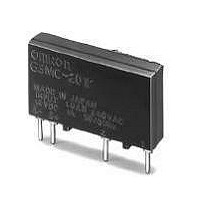
G3MC-202PL-VD DC12
Manufacturer Part Number
G3MC-202PL-VD DC12
Description
SOLID STATE RELAY
Manufacturer
Omron
Series
G3MCr
Datasheet
1.G3MC-101PL_DC5.pdf
(8 pages)
Specifications of G3MC-202PL-VD DC12
Circuit
SPST-NO (1 Form A)
Output Type
AC
Load Current
2A
Voltage - Input
9.6 ~ 14.4VDC
Voltage - Load
75 ~ 264 V
Mounting Type
Through Hole
Termination Style
PC Pin
Package / Case
4-SIP
Control Voltage Range
5 VDC to 24 VDC
Load Voltage Rating
264 V
Load Current Rating
2 A
Output Device
Triac
Mounting Style
SMD/SMT
Relay Type
Solid State
Lead Free Status / RoHS Status
Lead free / RoHS Compliant
On-state Resistance
-
Lead Free Status / Rohs Status
Lead free / RoHS Compliant
Other names
G3MC-202PL-VDDC12
G3MC202PLVDDC12
G3MC202PLVDDC12


Precautions
■ General Precautions
Do not touch the terminals of the SSR while power is being supplied
to the SSR. The terminals are charged with the power,
and an electric shock may be received by touching the terminals.
The built-in capacitor may have a residual voltage after the SSR
is turned off. Be sure to discharge the residual voltage before touch-
ing the terminals of the SSR, otherwise an electric shock
may be received.
■ Mounting
1. Make sure that no excessive voltage or current is imposed on or
2. Solder the terminals of the SSR properly under the required sol-
3. Do not short-circuit the load of the SSR while power is supplied to
■ Correct use
The terminals of the SSR are highly heat-conductive. Each terminal
must be soldered within 10 s at 260°C or within 5 s at 350°C.
The SSR is of a thin-profile construction. To maintain the vibration
resistance of the SSR, make sure that the space between the SSR
and PCB is 0.1 mm maximum. Lifting of the PCB can be prevented
by setting the hole diameter of the PCBs on both sides slightly
smaller than the actual terminal dimension.
Select the model without the zero-cross function when using the Unit
for phase control output.
The casing works as a heat sink. When mounting two or more Units
closely, make sure that the Units are properly ventilated by taking
ambient temperature rises into consideration. If Units are closely
mounted and used in places with no ventilation, the load current of
each Unit must be 1/2 of the rated load current.
flows to the input or output circuit of the SSR,
otherwise the SSR may malfunction or burn.
dering conditions. The SSR may be abnormally heated and burn
if power is supplied to the terminals soldered incorrectly.
the SSR. Do not short-circuit the power supply through the SSR.
The SSR may be damaged, malfunction, or burn if the load or
power supply is short-circuited.
■ Protective element
No overvoltage absorption element is built in. Therefore, if the G3MC
is connected to an inductive load, be sure to connect the overvoltage
absorption element.
G3MC-@@@PL (without Zero cross function)
G3MC-@@@P (with Zero cross function)
Input
Input
Phototriac
Phototriac
Solid State Relay
G3MC
Protective
element
(MOV)
Protective
element
(MOV)
Load
Load
Power
supply
Power
supply
381
Related parts for G3MC-202PL-VD DC12
Image
Part Number
Description
Manufacturer
Datasheet
Request
R

Part Number:
Description:
SOLID STATE RELAY
Manufacturer:
Omron
Datasheet:

Part Number:
Description:
SOLID STATE RELAY
Manufacturer:
Omron
Datasheet:

Part Number:
Description:
SOLID STATE RELAY
Manufacturer:
Omron
Datasheet:
Part Number:
Description:
SOLID STATE RELAY
Manufacturer:
Omron
Datasheet:

Part Number:
Description:
Solid State Relays 5VDC/100-240VAC 2A Built-in snubber
Manufacturer:
Omron
Datasheet:
Part Number:
Description:
Solid State Relays 12VDC/100-240VAC 2A Built-in snubber
Manufacturer:
Omron
Datasheet:
Part Number:
Description:
Solid State Relays 24VDC/100-240VAC 2A Built-in snubber
Manufacturer:
Omron
Datasheet:
Part Number:
Description:
Solid State Relays Phototriac 2A 24V VDE No Zero Crs
Manufacturer:
Omron
Datasheet:
Part Number:
Description:
Solid State Relays Phototriac 2A w/Ins 24V VDE No Zero Crs
Manufacturer:
Omron
Datasheet:

Part Number:
Description:
G6S-2GLow Signal Relay
Manufacturer:
Omron Corporation
Datasheet:
Part Number:
Description:
Compact, Low-cost, SSR Switching 5 to 20 A
Manufacturer:
Omron Corporation
Datasheet:
Part Number:
Description:
Manufacturer:
Omron Corporation
Datasheet: