XB4A-4035-D Omron, XB4A-4035-D Datasheet - Page 3
XB4A-4035-D
Manufacturer Part Number
XB4A-4035-D
Description
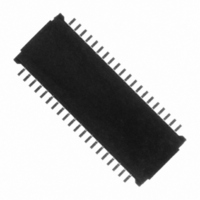
Board To FPC Connector
Manufacturer
Omron
Series
XB4Ar
Datasheet
1.XB4A-2435-D.pdf
(6 pages)
Specifications of XB4A-4035-D
Connector Type
Plug, Center Strip Contacts
Number Of Positions
40
Pitch
0.016" (0.40mm)
Number Of Rows
2
Mounting Type
Surface Mount
Contact Finish
Gold
Contact Finish Thickness
5.9µin (0.15µm)
Mated Stacking Heights
0.9mm
Height Above Board
0.030" (0.75mm)
Product Type
PCB
Number Of Positions / Contacts
40
Mounting Angle
Vertical
Mounting Style
SMD/SMT
Housing Material
Liquid Crystal Polymer
Contact Material
Spring Copper Alloy / Nickel Substrate
Contact Plating
Gold
Voltage Rating
50 V
Current Rating
0.3 A
Termination Style
Solder
Wire Type
FPC
Lead Free Status / RoHS Status
Lead free / RoHS Compliant
Features
-
Lead Free Status / Rohs Status
Lead free / RoHS Compliant
Other names
OR768TR
XB4A4035D
XB4A4035D
Available stocks
Company
Part Number
Manufacturer
Quantity
Price
Company:

Part Number:
XB4A-4035-D
Manufacturer:
AVAGO
Quantity:
670
Company:
Part Number:
XB4A-4035-D
Manufacturer:
Omron Electronics Inc-EMC Div
Quantity:
12 000


Safety Precautions
Precautions for Correct Use
For Operating
1. Regarding the connector stacking operation, it should be con-
2. Ensure that the connector stackings are fully seated.
3. Do not apply an extreme load when inserting or drawing out the
4. When stacking the plug and socket, press the back side of printed
5. When drawing out, hold the edge of the printed circuit board near
firmed there is no extreme displacement and tilt in the stacking
contact areas between a plug and a socket before the stacking
operation of the connectors.
• An incomplete stacking state may cause the failure of contact
connector.
• The connector may be damaged, resulting in faulty contacts.
circuit board mounted with them and then couple with as little
twisting force as possible.
• Doing so may cause the terminal and housing to change shape
the connector and remove as vertically as possible, as described
in the figure below.
• Drawing out the plug with too much force may have possibility to
reliability.
or the housing to crack.
change shape of terminal solder/housing crack.
Pitch direction
Row direction
0.4-mm Pitch Board to FPC Connector
6. Do not insert a foreign object such as a tweezers into the connec-
For Mounting
1. The reflow conditions are as stated in OMRON’s specifications
2. When mounting the connector by manual soldering, observe the
For Designing
1. When mounting the connector to the FPC, design the FPC so that
2. If the connector-mounted FPC is installed at a location or in any
3. Do not use plural connectors on same PCB.
4. When locating the connector on the printed circuit board, be sure
5. Ensure a metal mask thickness of t = 0.10 to 0.15 mm.
tor stacking contact area.
• Doing so may cause the plating peel off and deform the shape
and guidelines.
These conditions, however, depend on the type of solder, the
manufacturer, the amount of solder, the size of the circuit board,
and the other mounting materials.
following precautions to ensure contact reliability.
• Conditions for manual soldering: 350±10°C 3±1 sec
• Do not apply an excessive amount of solder. Excessive solder
• Do not apply the soldering iron to the mounting terminal. Doing
• Do not apply the soldering iron to any parts of the connector
extreme peel force should not be applied directly on to the con-
nector.
If the FPC bends near the connector, or if the FPC is used with
extreme peel force directly on to the connector, it may cause a
contact loss.
equipment that will subject the FPC to continuous shake or move-
ment, secure the FPC or take any countermeasure against FPC
disconnection from the connector.
• Doing so may cause solder and housing crack.
to allow space for the stacking operation.
The recommended open area of the metal mask is 90% of the
printed circuit board’s mating dimensions as shown in the dimen-
sional diagrams.
of the terminal.
will cause the flux creap.
so may cause the connectors to change shape.
other than the mount attachments. Doing so may cause the con-
nector to change shape.
XB4A/XB4B
39
Related parts for XB4A-4035-D
Image
Part Number
Description
Manufacturer
Datasheet
Request
R

Part Number:
Description:
Board To FPC Connector
Manufacturer:
Omron
Datasheet:

Part Number:
Description:
Board To FPC Connector
Manufacturer:
Omron
Datasheet:

Part Number:
Description:
G6S-2GLow Signal Relay
Manufacturer:
Omron Corporation
Datasheet:
Part Number:
Description:
Compact, Low-cost, SSR Switching 5 to 20 A
Manufacturer:
Omron Corporation
Datasheet:
Part Number:
Description:
Manufacturer:
Omron Corporation
Datasheet:
Part Number:
Description:
Manufacturer:
Omron Corporation
Datasheet:
Part Number:
Description:
Manufacturer:
Omron Corporation
Datasheet:
Part Number:
Description:
Manufacturer:
Omron Corporation
Datasheet:
Part Number:
Description:
Manufacturer:
Omron Corporation
Datasheet:
Part Number:
Description:
Manufacturer:
Omron Corporation
Datasheet: