MSR1560G ON Semiconductor, MSR1560G Datasheet

DIODE STD REC 15A 600V TO220AC

MSR1560G

Manufacturer Part Number
MSR1560G
Description
DIODE STD REC 15A 600V TO220AC
Manufacturer
ON Semiconductor
Series
SWITCHMODE™r
Datasheet

Specifications of MSR1560G

Voltage - Forward (vf) (max) @ If
1.8V @ 15A
Voltage - Dc Reverse (vr) (max)
600V
Current - Average Rectified (io)
15A
Current - Reverse Leakage @ Vr
15µA @ 600V
Diode Type
Standard
Speed
Fast Recovery =< 500ns, > 200mA (Io)
Reverse Recovery Time (trr)
45ns
Mounting Type
Through Hole
Package / Case
TO-220-2, TO-220AC
Product
Ultra Fast Recovery Rectifier
Configuration
Single Dual Cathode
Reverse Voltage
600 V
Forward Voltage Drop
1.8 V
Recovery Time
45 ns
Forward Continuous Current
15 A
Max Surge Current
100 A
Reverse Current Ir
15 uA
Mounting Style
Through Hole
Maximum Operating Temperature
+ 150 C
Minimum Operating Temperature
- 65 C
Lead Free Status / RoHS Status
Lead free / RoHS Compliant
Capacitance @ Vr, F
-
Lead Free Status / Rohs Status
Lead free / RoHS Compliant
Other names
MSR1560GOS

Available stocks

Company
Part Number
Manufacturer
Quantity
Price
Part Number:
MSR1560G
Manufacturer:
ON Semiconductor
Quantity:
2 529
Part Number:
MSR1560G
Manufacturer:
ON Semiconductor
Quantity:
1
Part Number:
MSR1560G
Manufacturer:
ON/安森美
Quantity:
20 000
MSR1560, MSRF1560
SWITCHMODEt Soft
Recovery Power Rectifier
hard−switched converter applications, especially for Power Factor
Correction application. It could also be used as a free wheeling diode
in variable speed motor control applications and switching mode
power supplies.
Features
Mechanical Characteristics:
Stresses exceeding Maximum Ratings may damage the device. Maximum
Ratings are stress ratings only. Functional operation above the Recommended
Operating Conditions is not implied. Extended exposure to stresses above the
Recommended Operating Conditions may affect device reliability.
MAXIMUM RATINGS
© Semiconductor Components Industries, LLC, 2008
September, 2008 − Rev. 6
THERMAL CHARACTERISTICS
Peak Repetitive Reverse Voltage
Working Peak Reverse Voltage
DC Blocking Voltage
Average Rectified Forward Current
(At Rated V
Peak Repetitive Forward Current (At Rated
V
Non−Repetitive Peak Surge Current
(Surge applied at rated load conditions,
halfwave, single phase, 60 Hz)
Operating Junction and Storage
Temperature Range
MSR1560: Thermal Resistance
MSRF1560: Thermal Resistance
These state−of−the−art devices are designed for boost converter or
Reverse Recovery Current (I
Leads Readily Solderable
260°C Max. for 10 Seconds
Soft Recovery with Low Reverse Recovery Charge (Q
Epoxy meets UL 94 V−0 @ 0.125 in
Low Forward Voltage
Low Leakage Current
High Temperature Glass Passivated Junction
Pb−Free Package is Available*
Case: Epoxy, Molded
Weight: 1.9 Grams (Approximately)
Finish: All External Surfaces Corrosion Resistant and Terminal
Lead Temperature for Soldering Purposes:
R
, Square Wave, 20 kHz,T
Junction−to−Case
Junction−to−Ambient
Junction−to−Case
Junction−to−Ambient
R
, T
C
Parameter
= 125°C)
Rating
C
= 125°C)
RRM
)
Symbol
Symbol
T
V
V
R
R
R
R
I
I
J
RWM
FRM
FSM
V
RRM
, T
I
qJC
qJA
qJC
qJA
O
R
stg
−65 to +150
Value
Value
72.8
4.25
600
100
1.6
15
30
75
RR
) and Peak
1
°C/W
°C/W
Unit
Unit
°C
V
A
A
A
MSR1560
MSR1560G
MSRF1560G
Device
1
15 AMPERES, 600 VOLTS
CASE 221B
TO−220AC
AY
3
MSR1560
STYLE 1
ORDERING INFORMATION
POWER RECTIFIER
A
Y
WW
G
KA
SOFT RECOVERY
KA
MARKING DIAGRAMS
WWG
http://onsemi.com
TO−220AC
TO−220AC
TO−220FP
1
3
(Pb−Free)
(Pb−Free)
= Assembly Location
= Year
= Work Week
= Pb−Free Package
= Diode Polarity
Package
4
Publication Order Number:
TO−220 FULLPAK
CASE 221E
1
STYLE 1
4
50 Units/Rail
3
50 Units/Rail
50 Units/Rail
MSRF1560
Shipping
AYWWG
MSR1560/D
KA
4

Related parts for MSR1560G

MSR1560G Summary of contents

Page 1

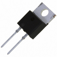
... J stg Symbol Value Unit °C/W R 1.6 qJC R 72.8 qJA °C/W Device R 4.25 qJC 75 R qJA MSR1560 MSR1560G MSRF1560G 1 http://onsemi.com SOFT RECOVERY POWER RECTIFIER 15 AMPERES, 600 VOLTS TO−220AC TO−220 FULLPAK CASE 221B CASE 221E STYLE 1 STYLE 1 MARKING DIAGRAMS ...

Page 2

ELECTRICAL CHARACTERISTICS Characteristic Instantaneous Forward Voltage (Note 1) (I Maximum Typical Instantaneous Reverse Current (V = 600 V) R Maximum Typical Reverse Recovery Time (Note Maximum Typical Typical Recovery Softness Factor (V = ...

Page 3

I @ 150°C R 100 I @ 100° 25°C R 0.1 0 100 200 300 V , REVERSE VOLTAGE (VOLTS) R Figure 3. Maximum Reverse Current Square Wave 10 ...

Page 4

T vs. di/dt @ 25° vs. di/dt @ 25° 100 175 dI/dt (A/mS) Figure 9. Typical Trr vs. di/ ...

Page 5

ID = 0.5 1 0.1 0.05 0.01 Single Pulse 0.1 0.0001 0.001 Figure 14. Transient Thermal Response 0.5 0.2 1.0 0.1 0.05 0.02 0.1 0.01 0.01 SINGLE PULSE 0.001 0.000001 0.00001 0.0001 Figure 15. Thermal Response, ...

Page 6

D = 0.5 0.2 10 0.1 0.05 0.02 1.0 0.01 0.1 0.01 SINGLE PULSE 0.001 0.000001 0.00001 0.0001 Figure 16. Thermal Response, (MSRF1560) Junction−to−Ambient (R P (pk DUTY CYCLE 0.001 0.01 0.1 ...

Page 7

... Opportunity/Affirmative Action Employer. This literature is subject to all applicable copyright laws and is not for resale in any manner. PUBLICATION ORDERING INFORMATION LITERATURE FULFILLMENT: Literature Distribution Center for ON Semiconductor P.O. Box 5163, Denver, Colorado 80217 USA Phone: 303−675−2175 or 800−344−3860 Toll Free USA/Canada Fax: 303− ...

Related keywords