MURS230T3G ON Semiconductor, MURS230T3G Datasheet

DIODE ULTRA FAST 2A 300V SMB

MURS230T3G

Manufacturer Part Number
MURS230T3G
Description
DIODE ULTRA FAST 2A 300V SMB
Manufacturer
ON Semiconductor
Datasheet

Specifications of MURS230T3G

Voltage - Forward (vf) (max) @ If
1.3V @ 2A
Voltage - Dc Reverse (vr) (max)
300V
Current - Average Rectified (io)
2A
Current - Reverse Leakage @ Vr
5µA @ 300V
Diode Type
Standard
Speed
Fast Recovery =< 500ns, > 200mA (Io)
Reverse Recovery Time (trr)
65ns
Mounting Type
Surface Mount
Package / Case
DO-214AA, SMB
Product
Ultra Fast Recovery Rectifier
Configuration
Single
Reverse Voltage
300 V
Forward Voltage Drop
1.15 V
Recovery Time
65 ns
Forward Continuous Current
2 A
Max Surge Current
35 A
Reverse Current Ir
5 uA
Mounting Style
SMD/SMT
Maximum Operating Temperature
+ 175 C
Minimum Operating Temperature
- 65 C
Lead Free Status / RoHS Status
Lead free / RoHS Compliant
Capacitance @ Vr, F
-
Lead Free Status / Rohs Status
Lead free / RoHS Compliant
Other names
MURS230T3GOS

Available stocks

Company
Part Number
Manufacturer
Quantity
Price
Part Number:
MURS230T3G
Manufacturer:
ON Semiconductor
Quantity:
6 760
Part Number:
MURS230T3G
Manufacturer:
ON Semiconductor
Quantity:
17 150
Part Number:
MURS230T3G
Manufacturer:
ON/安森美
Quantity:
20 000
MURS230T3, MURS240T3
Surface Mount
Ultrafast Power Rectifiers
free wheeling and protection diodes in surface mount applications
where compact size and weight are critical to the system.
Features
Mechanical Characteristics:
Stresses exceeding Maximum Ratings may damage the device. Maximum
Ratings are stress ratings only. Functional operation above the Recommended
Operating Conditions is not implied. Extended exposure to stresses above the
Recommended Operating Conditions may affect device reliability.
MAXIMUM RATINGS
THERMAL CHARACTERISTICS
© Semiconductor Components Industries, LLC, 2011
January, 2011 − Rev. 7
Peak Repetitive Reverse Voltage
Average Rectified Forward Current
Non−Repetitive Peak Surge Current
(Surge applied at rated load conditions
halfwave, single phase, 60 Hz)
Operating Junction Temperature Range
Thermal Resistance, Junction−to−Lead
(T
Ideally suited for high voltage, high frequency rectification, or as
Leads are Readily Solderable
260°C Max. for 10 Seconds
Small Compact Surface Mountable Package with J−Bend Leads
Rectangular Package for Automated Handling
High Temperature Glass Passivated Junction
Low Forward Voltage Drop (0.95 Volts Max @ 2.0 A, T
Pb−Free Packages are Available
Case: Epoxy, Molded
Weight: 95 mg (Approximately)
Finish: All External Surfaces Corrosion Resistant and Terminal
Lead and Mounting Surface Temperature for Soldering Purposes:
Polarity: Polarity Band Indicates Cathode Lead
Working Peak Reverse Voltage
DC Blocking Voltage
@ T
@ T
L
= 25°C)
L
L
= 150°C
= 125°C
Rating
Rating
MURS230T3
MURS240T3
Symbol
Symbol
V
V
I
I
R
F(AV)
FSM
RWM
V
RRM
T
qJL
R
J
−65 to +175
Value
Max
300
400
1.0
2.0
35
13
J
= 150°C)
1
°C/W
Unit
Unit
°C
V
A
A
†For information on tape and reel specifications,
MURS230T3
MURS230T3G
MURS240T3
MURS240T3G
including part orientation and tape sizes, please
refer to our Tape and Reel Packaging Specifications
Brochure, BRD8011/D.
2 AMPERES, 300−400 VOLTS
Device
(Note: Microdot may be in either location)
ULTRAFAST RECTIFIERS
A
Y
WW
U2x
G
ORDERING INFORMATION
MARKING DIAGRAM
http://onsemi.com
= Assembly Location
= Year
= Work Week
= Device Code
= Pb−Free Package
x= F for MURS230T3
CASE 403A
(Pb−Free)
(Pb−Free)
= G for MURS240T3
Package
SMB
SMB
SMB
SMB
SMB
AYWW
U2x G
Publication Order Number:
G
2500 Tape & Reel
2500 Tape & Reel
2500 Tape & Reel
2500 Tape & Reel
MURS230T3/D
Shipping

Related parts for MURS230T3G

MURS230T3G Summary of contents

Page 1

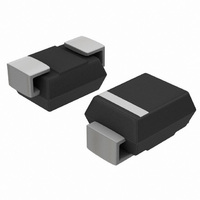
... G for MURS240T3 G = Pb−Free Package (Note: Microdot may be in either location) ORDERING INFORMATION Device Package Shipping MURS230T3 SMB 2500 Tape & Reel MURS230T3G SMB 2500 Tape & Reel (Pb−Free) MURS240T3 SMB 2500 Tape & Reel MURS240T3G SMB 2500 Tape & Reel (Pb−Free) ...

Page 2

ELECTRICAL CHARACTERISTICS Maximum Instantaneous Forward Voltage (Note 2 25° 2 150° Maximum Instantaneous Reverse Current (Note 1) (Rated DC Voltage 25°C) J (Rated ...

Page 3

T = 175° 150° 100°C J 0.1 0. 25°C J 0.001 0 50 100 150 200 250 V , REVERSE VOLTAGE (VOLTS) R Figure 3. Typical Reverse Current* * ...

Page 4

NOTE: TYPICAL CAPACITANCE 4.0 8 REVERSE VOLTAGE (VOLTS) R Figure 6. Typical Capacitance 10 RATED VOLTAGE APPLIED ...

Page 5

... Pb−Free strategy and soldering details, please download the ON Semiconductor Soldering and Mounting Techniques Reference Manual, SOLDERRM/D. ON Semiconductor and are registered trademarks of Semiconductor Components Industries, LLC (SCILLC). SCILLC reserves the right to make changes without further notice to any products herein ...

Related keywords