MBR0530T3 ON Semiconductor, MBR0530T3 Datasheet

DIODE SCHOTTKY 0.5A 30V SOD-123

MBR0530T3

Manufacturer Part Number
MBR0530T3
Description
DIODE SCHOTTKY 0.5A 30V SOD-123
Manufacturer
ON Semiconductor
Datasheet

Specifications of MBR0530T3

Voltage - Forward (vf) (max) @ If
430mV @ 500mA
Voltage - Dc Reverse (vr) (max)
30V
Current - Average Rectified (io)
500mA
Current - Reverse Leakage @ Vr
130µA @ 30V
Diode Type
Schottky
Speed
Fast Recovery =< 500ns, > 200mA (Io)
Mounting Type
Surface Mount
Package / Case
SOD-123
Lead Free Status / RoHS Status
Contains lead / RoHS non-compliant
Reverse Recovery Time (trr)
-
Capacitance @ Vr, F
-

Available stocks

Company
Part Number
Manufacturer
Quantity
Price
Part Number:
MBR0530T3G
Manufacturer:
ON
Quantity:
30 000
Part Number:
MBR0530T3G
Manufacturer:
ON/安森美
Quantity:
20 000
MBR0530T1, MBR0530T3
Surface Mount
Schottky Power Rectifier
Plastic SOD−123 Package
area metal−to−silicon power diode. Ideally suited for low voltage,
high frequency rectification or as free wheeling and polarity
protection diodes in surface mount applications where compact size
and weight are critical to the system. This package also provides an
easy to work with alternative to leadless 34 package style. These
state−of−the−art devices have the following features:
Features
Mechanical Characteristics
MAXIMUM RATINGS
© Semiconductor Components Industries, LLC, 2009
August, 2009 − Rev. 5
Stresses exceeding Maximum Ratings may damage the device. Maximum
Ratings are stress ratings only. Functional operation above the Recommended
Operating Conditions is not implied. Extended exposure to stresses above the
Recommended Operating Conditions may affect device reliability.
Peak Repetitive Reverse Voltage
Working Peak Reverse Voltage
DC Blocking Voltage
Average Rectified Forward Current
(Rated V
Non−Repetitive Peak Surge Current
(Surge Applied at Rated Load Conditions
Halfwave, Single Phase, 60 Hz)
Storage Temperature Range
Operating Junction Temperature
Voltage Rate of Change (Rated V
ESD Rating:
The MBR0530T1/3 uses the Schottky Barrier principle with a large
Reel Options:
Leads are Readily Solderable
260°C Max. for 10 Seconds
Guardring for Stress Protection
Low Forward Voltage
125°C Operating Junction Temperature
Epoxy Meets UL 94, V−0 @ 0.125 in
Package Designed for Optimal Automated Board Assembly
Pb−Free Packages are Available
Reel Options:
Polarity Designator: Cathode Band
Weight: 11.7 mg (approximately)
Case: Epoxy, Molded
Finish: All External Surfaces Corrosion Resistant and Terminal
Lead and Mounting Surface Temperature for Soldering Purposes:
R
, T
L
= 100°C)
Human Body Model = 3B
Rating
MBR0530T1 = 3,000 per 7 in reel / 8 mm tape
MBR0530T3 = 10,000 per 13 in reel / 8 mm tape
Machine Model = C
R
)
Symbol
V
V
I
dv/dt
I
F(AV)
T
FSM
RWM
RRM
V
T
stg
R
J
−65 to +150
−65 to +125
> 8000
Value
> 400
1000
0.5
5.5
30
1
Unit
V/ms
°C
°C
V
A
A
V
See detailed ordering and shipping information in the package
dimensions section on page 3 of this data sheet.
(Note: Microdot may be in either location)
SCHOTTKY BARRIER
ORDERING INFORMATION
B3
M
G
MARKING DIAGRAM
0.5 AMPERES
http://onsemi.com
RECTIFIER
30 VOLTS
CASE 425
SOD−123
STYLE 1
= Device Code
= Date Code
= Pb−Free Package
B3 M G
Publication Order Number:
G
MBR0530T1/D

Related parts for MBR0530T3

MBR0530T3 Summary of contents

Page 1

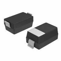
... Package Designed for Optimal Automated Board Assembly • Pb−Free Packages are Available Mechanical Characteristics • Reel Options: MBR0530T1 = 3,000 per 7 in reel / 8 mm tape Reel Options: MBR0530T3 = 10,000 per 13 in reel / 8 mm tape • Polarity Designator: Cathode Band • Weight: 11.7 mg (approximately) • Case: Epoxy, Molded • ...

Page 2

THERMAL CHARACTERISTICS Rating Thermal Resistance − Junction−to−Ambient (Note 1) Thermal Resistance − Junction−to−Lead ELECTRICAL CHARACTERISTICS Maximum Instantaneous Forward Voltage (Note 0.1 Amps 25° 0.5 Amps 25° Maximum ...

Page 3

... LEAD TEMPERATURE (°C) Figure 4. Current Derating (Lead) ORDERING INFORMATION Device MBR0530T1 MBR0530T1G MBR0530T3 MBR0530T3G †For information on tape and reel specifications, including part orientation and tape sizes, please refer to our Tape and Reel Packaging Specifications Brochure, BRD8011/D. 0.35 0.315 T = 125°C J ...

Page 4

... *For additional information on our Pb−Free strategy and soldering details, please download the ON Semiconductor Soldering and Mounting Techniques Reference Manual, SOLDERRM/D. ON Semiconductor and are registered trademarks of Semiconductor Components Industries, LLC (SCILLC). SCILLC reserves the right to make changes without further notice to any products herein. SCILLC makes no warranty, representation or guarantee regarding the suitability of its products for any particular purpose, nor does SCILLC assume any liability arising out of the application or use of any product or circuit, and specifically disclaims any and all liability, including without limitation special, consequential or incidental damages. “ ...

Related keywords