IXGA20N60B IXYS, IXGA20N60B Datasheet - Page 2
IXGA20N60B
Manufacturer Part Number
IXGA20N60B
Description
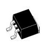
IGBT 40A 600V TO-263AA
Manufacturer
IXYS
Series
HiPerFAST™r
Datasheet
1.IXGP20N60B.pdf
(4 pages)
Specifications of IXGA20N60B
Voltage - Collector Emitter Breakdown (max)
600V
Vce(on) (max) @ Vge, Ic
2V @ 15V, 20A
Current - Collector (ic) (max)
40A
Power - Max
150W
Input Type
Standard
Mounting Type
Surface Mount
Package / Case
D²Pak, TO-263 (2 leads + tab)
Channel Type
N
Configuration
Single
Collector-emitter Voltage
600V
Collector Current (dc) (max)
40A
Gate To Emitter Voltage (max)
±20V
Package Type
TO-263AA
Pin Count
2 +Tab
Mounting
Surface Mount
Operating Temperature (max)
150C
Operating Temperature Classification
Military
Vces, (v)
600
Ic25, Tc=25°c, Igbt, (a)
40
Ic90, Tc=90°c, Igbt, (a)
20
Ic110, Tc=110°c, Igbt, (a)
-
Vce(sat), Max, Tj=25°c, Igbt, (v)
1.7
Tfi, Typ, Tj=25°c, Igbt, (ns)
100
Eoff, Typ, Tj=125°c, Igbt, (mj)
1.2
Rthjc, Max, Igbt, (°c/w)
0.83
If, Tj=110°c, Diode, (a)
-
Rthjc, Max, Diode, (ºc/w)
-
Package Style
TO-263 (D2 PAK)
Lead Free Status / RoHS Status
Lead free / RoHS Compliant
Igbt Type
-
Lead Free Status / Rohs Status
Compliant


© 2000 IXYS All rights reserved
Symbol
g
C
C
C
Q
Q
Q
t
t
E
t
t
E
t
t
E
t
t
E
R
R
d(on)
d(off)
d(on)
d(off)
ri
fi
ri
fi
fs
on
on
oes
off
off
thJC
thCK
ies
res
g
ge
gc
Test Conditions
I
Pulse test, t £ 300 ms, duty cycle £ 2 %
C
= I
V
I
(TO-220)
Inductive load, T
I
V
Remarks: Switching times may increase
for V
increased R
Inductive load, T
I
V
Remarks: Switching times may
increase for V
higher T
C
C
C
CE
CE
CE
= I
= I
= I
C90
= 25 V, V
= 0.8 V
= 0.8 V
C90
C90
CE
C90
; V
, V
, V
(Clamp) > 0.8 • V
, V
CE
J
or increased R
GE
GE
GE
= 10 V,
CES
CES
G
= 15 V, V
= 15 V, L = 100 mH,
= 15 V, L = 100 mH
GE
CE
, R
, R
= 0 V, f = 1 MHz
(Clamp) > 0.8 • V
G
G
J
J
= R
= R
= 25°C
= 125°C
CE
off
off
G
= 0.5 V
CES
= 10 W
= 10 W
IXYS MOSFETS and IGBTs are covered by one or more of the following U.S. patents:
4,835,592
4,850,072
(T
Min. Recommended Footprint
, higher T
J
= 25°C, unless otherwise specified)
CES
CES
4,881,106
4,931,844
,
J
or
min.
Characteristic Values
9
5,017,508
5,034,796
1500
typ.
0.15
0.15
0.25
175
150
100
220
140
0.7
1.2
17
40
90
11
30
15
35
15
35
max.
0.83 K/W
5,049,961
5,063,307
200
150
1.0 mJ
K/W
mJ
mJ
mJ
nC
nC
nC
pF
pF
pF
ns
ns
ns
ns
ns
ns
ns
ns
S
5,187,117
5,237,481
TO-220 AB (IXGP) Outline
TO-263 AA (IXGA) Outline
Dim.
Dim.
A
A1
b
b2
c
c2
D
D1
E
E1
e
L
L1
L2
L3
L4
R
5,486,715
5,381,025
A
B
C
D
E
F
G
H
J
K
M
N
Q
R
12.70 13.97 0.500 0.550
14.73 16.00 0.580 0.630
14.61
9.91 10.66 0.390 0.420
3.54
5.85
2.54
1.15
2.79
0.64
2.54
4.32
1.14
0.35
2.29
Min.
4.06
2.03
0.51
1.14
0.46
1.14
8.64
7.11
9.65
6.86
2.54
2.29
1.02
1.27
0.46
Min.
Millimeter
Millimeter
0
IXGA 20N60B
IXGP 20N60B
10.29
15.88
Max.
BSC 0.100
4.08 0.139 0.161
6.85 0.230 0.270
3.18 0.100 0.125
1.65 0.045 0.065
5.84 0.110 0.230
1.01 0.025 0.040
4.82 0.170 0.190
1.39 0.045 0.055
0.56 0.014 0.022
2.79 0.090 0.110
Max.
4.83
2.79
0.99
1.40
0.74
1.40
9.65
8.13
8.13
BSC
2.79
1.40
1.78
0.38
0.74
.160
.080
.020
.045
.018
.045
.340
.280
.380
.270
.100
.575
.090
.040
.050
.018
Min.
Min.
Inches
0
Inches
Max.
.190
.110
.039
.055
.029
.055
.380
.320
.405
.320
BSC
.625
.110
.055
.070
.015
.029
Max.
BSC
2 - 4
Related parts for IXGA20N60B
Image
Part Number
Description
Manufacturer
Datasheet
Request
R

Part Number:
Description:
TRANS IGBT CHIP N-CH 1000V 30A 4TO-263 AA
Manufacturer:
IXYS Corporation
Part Number:
Description:
TRANS IGBT CHIP N-CH 600V 24A 3TO-263AA
Manufacturer:
IXYS Corporation
Part Number:
Description:
TRANS IGBT CHIP N-CH 1200V 30A 4TO-263 AA
Manufacturer:
IXYS Corporation
Part Number:
Description:
TRANS IGBT CHIP N-CH 600V 48A 3TO-263AA
Manufacturer:
IXYS Corporation
Part Number:
Description:
TRANS IGBT CHIP N-CH 1000V 40A 4TO-263 AA
Manufacturer:
IXYS Corporation

Part Number:
Description:
HiPerFET Power MOSFETs
Manufacturer:
IXYS Corporation
Datasheet:
Part Number:
Description:
J-K-Type Flip-Flop
Manufacturer:
IXYS Corporation
Datasheet: