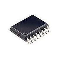
SI2401-FSR Silicon Laboratories Inc, SI2401-FSR Datasheet - Page 22

SI2401-FSR
Manufacturer Part Number
SI2401-FSR
Description
Telecom Line Management ICs 2400b/s System Side 3rd Gen DAA Tech
Manufacturer
Silicon Laboratories Inc
Type
Integrated Global DAAr
Specifications of SI2401-FSR
Product
Modem Module
Supply Voltage (min)
3 V
Supply Current
15 mA
Maximum Operating Temperature
+ 100 C
Minimum Operating Temperature
- 10 C
Mounting Style
SMD/SMT
Package / Case
SOIC-16
Lead Free Status / RoHS Status
Lead free / RoHS Compliant
Available stocks
Company
Part Number
Manufacturer
Quantity
Price
Company:
Part Number:
SI2401-FSR
Manufacturer:
GENNUM
Quantity:
7
Part Number:
SI2401-FSR
Manufacturer:
SILICONLABS/芯科
Quantity:
20 000
Si2401
The method of transmitting HDLC frames is as follows:
1. After the call is connected, the host should begin
2. When the frame is complete, the host should simply
3. When the Si2401 is ready to send the next byte, if it
4. After transmitting the first stop flag, the Si2401
The method of receiving HDLC frames is as follows:
1. After the call is connected, the Si2401 searches for
22
(or bit 9)
sending the frame data to the Si2401 using the CTS
flow control to ensure data synchronicity.
stop sending data to the Si2401. Since the Si2401
does not yet recognize the end-of-frame, it expects
an extra byte and asserts CTS as shown in
Figure 4A. If CTS is used to cause a host interrupt,
this final interrupt should be ignored by the host.
has not yet received any data from the host, it
recognizes this as an end-of-frame, raises CTS,
calculates the final CRC code, transmits the code,
and begins transmitting stop flags.
lowers CTS indicating that it is ready to receive the
next frame from the host. At this point, the process
repeats as in Step 1.
flag data. Then, once the first non-flag word is
detected, the CRC is continuously computed, and
the data is sent across the UART (8-bit data or 9-bit
data mode) to the host after removing the HDLC
zero-bit insertion. The DTE rate of the host must be
at least as high as that of data transmission. HDLC
mode only works with 8-bit data words; the ninth bit
is used only for escape on TXD and end-of-frame
received (EOFR) on RXD.
EOFR
RXD
CTS
TXD
Si2400 ready for byte 1 of frame N
Start
Host begins frame N
Note: Figure not to scale.
Receive Data
Start
Stop
(CTS used as normal flow control.)
Start
Frame N
Figure 4. HDLC Timing
CRC Byte 1
A. Frame Transmit
B. Frame Receive
Rev. 1.0
Stop
2. When the Si2401 detects the stop flag, it sends the
3. When the next frame of data is detected, EOFR is
To summarize, when receiving HDLC frames, the host
begins receiving data asynchronously from the Si2401.
When each byte is received, the host should check the
EOFR pin (or the ninth bit). If the EOFR pin (or the ninth
bit) is low, the data is valid frame data. If the EOFR pin
(or the ninth bit) is high, the data is a frame result word.
last data word in the frame as well as the two CRC
bytes and determines if the CRC checksum
matches. Thus, the last two bytes are not frame data
but are the CRC bytes, which can be discarded by
the host. If the checksum matches, the Si2401
echoes “G” (good). If the checksum does not match,
the Si2401 echoes “e” (error). Additionally, if the
Si2401 detects an abort (seven or more contiguous
ones), it echoes an “A”.
When the “G”, “e”, or “A” (referred to as a frame
result word) is sent, the Si2401 raises the EOFR
(end of frame receive) pin (see Figure 4B). The
GPIO1 pin must be configured as EOFR by setting
SE4[3] (GPE) = 1
pin to indicate that the byte is a frame result word, if
in 9-bit data mode (set S15[0] (NBE) = 1
bit is raised if the byte is a frame result word. To
program this mode, set S0C[3] (9BF) = 1
SE0[3] (ND) = 1.
lowered, and the process repeats at Step 1
Host finished sending frame N
Start
Stop
Si2401 detects end of frame N.
CRC Byte 2
Si2401 ready for byte 1
of frame N + 1.
b
. In addition to using the EOFR
Stop
Host begins frame N + 1
Start
Start
Frame Result Word
Frame N + 1
b
b
), the ninth
and
b
Stop
.


