IXTP18P10T IXYS, IXTP18P10T Datasheet

MOSFET P-CH 100V 18A TO-220

IXTP18P10T

Manufacturer Part Number
IXTP18P10T
Description
MOSFET P-CH 100V 18A TO-220
Manufacturer
IXYS
Series
TrenchP™r
Datasheet

Specifications of IXTP18P10T

Fet Type
MOSFET P-Channel, Metal Oxide
Fet Feature
Standard
Rds On (max) @ Id, Vgs
120 mOhm @ 500mA, 10V
Drain To Source Voltage (vdss)
100V
Current - Continuous Drain (id) @ 25° C
18A
Vgs(th) (max) @ Id
4.5V @ 250µA
Gate Charge (qg) @ Vgs
39nC @ 10V
Input Capacitance (ciss) @ Vds
2100pF @ 25V
Power - Max
83W
Mounting Type
Through Hole
Package / Case
TO-220
Vdss, Max, (v)
-100
Id(cont), Tc=25°c, (a)
-18
Rds(on), Max, Tj=25°c, (?)
0.12
Ciss, Typ, (pf)
2100
Qg, Typ, (nc)
39
Trr, Typ, (ns)
62
Trr, Max, (ns)
-
Pd, (w)
83
Rthjc, Max, (k/w)
1.5
Package Style
TO-220
Lead Free Status / RoHS Status
Lead free / RoHS Compliant
Symbol
V
V
V
V
I
I
I
E
P
T
T
T
T
T
M
Weight
Symbol
(T
BV
V
I
I
R
TrenchP
Power MOSFET
P-Channel Enhancement Mode
Avalanche Rated
© 2010 IXYS CORPORATION, All Rights Reserved
D25
DM
A
GSS
DSS
DSS
DGR
GSS
GSM
AS
D
J
JM
stg
L
SOLD
GS(th)
DS(on)
d
J
DSS
= 25°C, Unless Otherwise Specified)
Test Conditions
T
T
Continuous
Transient
T
T
T
T
T
1.6mm (0.062 in.) from Case for 10s
Plastic Body for 10s
Mounting Torque (TO-220)
TO-252
TO-263
TO-220
Test Conditions
V
V
V
V
V
J
J
C
C
C
C
C
GS
DS
GS
DS
GS
TM
= 25°C to 150°C
= 25°C to 150°C, R
= 25°C
= 25°C, Pulse Width Limited by T
= 25°C
= 25°C
= 25°C
= 0V, I
= V
= ± 15V, V
= V
= -10V, I
GS
DSS
, I
D
, V
D
= - 250μA
D
= - 250μA
GS
= 0.5 • I
DS
= 0V
= 0V
D25
GS
, Note 1
= 1MΩ
T
J
= 125°C
JM
IXTA18P10T
IXTY18P10T
IXTP18P10T
-55 ... +150
-55 ... +150
-100
- 2.5
Characteristic Values
Min.
Maximum Ratings
1.13 / 10
-100
-100
0.35
2.50
3.00
- 60
200
150
300
260
±15
±25
-18
-18
83
Typ.
- 4.5
-100 μA
Nm/lb.in.
Max.
120 mΩ
±50 nA
- 3 μA
mJ
°C
°C
°C
°C
°C
W
V
V
V
V
V
A
A
A
V
g
g
g
V
I
R
TO-252 (IXTY)
TO-263 AA (IXTA)
TO-220AB (IXTP)
G = Gate
S = Source
Features
Advantages
Applications
D25
Avalanche Rated
International Standard Packages
Extended FBSOA
Fast Intrinsic Diode
Low R
Easy to Mount
Space Savings
High Power Density
High-Side Switching
Push Pull Amplifiers
DC Choppers
Automatic Test Equipment
Current Regulators
Battery Charger Applications
DS(on)
DSS
DS(ON)
G
D S
≤ ≤ ≤ ≤ ≤
=
=
G
and Q
G
D
Tab = Drain
S
S
D (Tab)
-100V
-18A
D (Tab)
= Drain
G
D (Tab)
120mΩ Ω Ω Ω Ω
DS99966B(11/10)

Related parts for IXTP18P10T

IXTP18P10T Summary of contents

Page 1

... GSS DSS DS DSS -10V 0.5 • I DS(on © 2010 IXYS CORPORATION, All Rights Reserved IXTY18P10T IXTA18P10T IXTP18P10T Maximum Ratings -100 = 1MΩ -100 GS ±15 ±25 - -18 200 83 -55 ... +150 150 -55 ... +150 300 260 1. 0.35 2.50 3.00 Characteristic Values Min. Typ. -100 - 2 ...

Page 2

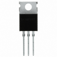
... L3 2.54 Max. - TO-220 Outline -1 Pins Gate 3 - Source 6,404,065 B1 6,683,344 6,727,585 6,534,343 6,710,405 B2 6,759,692 6,583,505 6,710,463 6,771,478 B2 7,071,537 IXTP18P10T 2,4 - Drain Inches Min. Max. 2.38 0.086 0.094 1.14 0.035 0.045 0 0.13 0 0.005 0.89 0.025 0.035 1.14 0.030 0.045 5.46 0.205 0.215 ...

Page 3

... J -30 -35 -40 -45 -50 -55 IXTY18P10T IXTA18P10T Fig. 2. Extended Output Characteristics @ -10V -10 - Volts DS Fig Normalized to I DS(on) Junction Temperature V = -10V -50 - Degrees Centigrade J Fig. 6. Maximum Drain Current vs. Case Temperature - -50 - Degrees Centigrade J IXTP18P10T = 25ºC J -20 - -18A 100 125 150 75 100 125 150 ...

Page 4

... IXTY18P10T IXTA18P10T Fig. 8. Transconductance -10 -12 - Amperes D Fig. 10. Gate Charge - 50V -1mA NanoCoulombs G Fig. 12. Forward-Bias Safe Operating Area R Limit DS(on 150º 25ºC C Single Pulse - Volts DS IXTP18P10T 40ºC J 25ºC 125ºC -16 -18 -20 -22 - 25µs 100µs 1ms 10ms 100ms - 100 - 1000 ...

Page 5

... 125º -10 -11 -12 -13 - Amperes D Fig. 16. Resistive Turn-off Switching Times vs. Junction Temperature 10Ω 50V -18A Degrees Centigrade J Fig. 18. Resistive Turn-off Switching Times vs. Gate Resistance d(off 125º -10V 50V 9A, -18A Ohms G IXTP18P10T -15 -16 -17 - d(off -10V 105 115 125 110 100 ...

Page 6

... IXYS Reserves the Right to Change Limits, Test Conditions, and Dimensions. Fig. 19. Maximum Transient Thermal Impedance 0.001 0.01 Pulse Width - Seconds IXTY18P10T IXTA18P10T IXTP18P10T 0.1 1 IXYS REF: T_18P10T(A1)11-05-10-A 10 ...

Related keywords