XS5C-D4S2 Omron, XS5C-D4S2 Datasheet - Page 16
XS5C-D4S2
Manufacturer Part Number
XS5C-D4S2
Description
Sensor I/O Connector
Manufacturer
Omron
Series
XS5r
Datasheet
1.XS5F-D421-D80-A.pdf
(18 pages)
Specifications of XS5C-D4S2
Connector Type
Receptacle, Female Sockets
Number Of Positions
4
Mounting Type
Free Hanging (In-Line), Right Angle
Termination
Screw
Fastening Type
Bayonet Lock
Orientation
Keyed
Ingress Protection
IP67 - Dust Tight, Waterproof
Shell Material, Finish
Brass, Nickel Plated
Product Type
Connectors
Contact Style
Socket (Female)
Shell Style
Receptacle
Number Of Positions / Contacts
4
Mounting Style
Free Hanging
Termination Style
Screw
Leaded Process Compatible
Yes
Contact Material
Brass
Connector Mounting
Free Hanging
No. Of Contacts
4
Contact Termination
Screw
Gender
Receptacle
Contact Gender
Socket (Female)
Contact Plating
Gold
Rohs Compliant
Yes
Lead Free Status / RoHS Status
Lead free / RoHS Compliant
Features
-
Shell Size - Insert
-
Shell Size, Military
-
Lead Free Status / Rohs Status
Lead free / RoHS Compliant
Other names
OR795
XS5CD4S2
XS5CD4S2


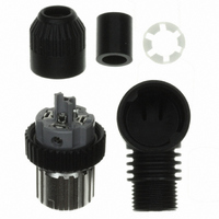
(5) Mounting Cap
Note: If the cap is not tighten securely enough, the degree of
(6) After Assembly
Recommended Cables
When connecting a commercially available cable to a connector
assembly, use a cable with an outside diameter of 3 to 6 mm and core
sizes of 0.18 to 0.75 mm
maximum for soldering connectors.
Connector Arrangement
For safety, when constructing a connection system between a Sensor
and panel with a connector, make sure that the connector plug is on
the Sensor side and the connector socket is on the panel side (i.e.,
the female pins are located on the power-supply side).
• Align the triangular marks on the pin block and cover and insert the
• Press them together firmly (0.39 to 0.49 N·m) until the pin block
• After mounting the cover to the pin block and the cover snaps into
• After fully tightening the cap, length A should be approximately one
For 6-mm-dia. cable
For 4-mm-dia. cable
For 3-mm-dia. cable
• Confirm the insulation between cores after completing assembly.
pin block into the cover.
does not come out of the cover.
place, tighten the cap securely by hand within a torque of 0.39 and
0.49 N·m.
of the following according to the cable external diameter and the
Connector model.
Sensor Side
Pin Block
(Screw-mounting Connectors)
(Plug)
protection (IP67) may not be maintained or vibration may
cause the cap to become loose. Do not tighten the cap with
pliers or similar tools; they may damage the cap.
Connector
Cover lock
(Socket)
Connecting Cable
2
for crimping connectors and 0.5 mm
Triangle mark
Pin block
6 mm
---
---
1
Cable external diameter (mm)
Cover
A
5 mm
(Plug)
---
0
2
Cap
Panel Side
(Power-supply Side)
4 mm
---
1
2
(Socket)
3 mm
2
---
---
1
Connecting the XS5
1. Connecting the XS5 Plug and Socket
2. Connecting the XS5 and XS2
• Align the projection on the plug cover with the polarity key on the
• Hold the knurled socket grip, then insert the projection on the plug
• Turn the knurled grips of the socket clockwise approximately 45
• Align the projection on the plug cover with the polarity key on the
• In the same way as when connecting two XS2 Connectors, screw
• Use your fingers to tighten the Connectors sufficiently.
socket, then insert the plug all the way in.
into the groove of the socket.
degrees in respect to the plug. A click will indicate that the
Connectors are locked. The locking condition can also be
confirmed by the alignment marks on the plug and socket.
socket, then insert the plug all the way in.
the knurled grip in the clockwise direction.
Alignment marks
Polarity key
Protrusion on
cover aligns with
polarity key.
XS5
16
Related parts for XS5C-D4S2
Image
Part Number
Description
Manufacturer
Datasheet
Request
R

Part Number:
Description:
Waterproof Sensor Connector
Manufacturer:
Omron
Datasheet:
Part Number:
Description:
Sensor I/O Connector
Manufacturer:
Omron
Datasheet:

Part Number:
Description:
Sensor I/O Connector
Manufacturer:
Omron
Datasheet:
Part Number:
Description:
Sensor I/O Connector
Manufacturer:
Omron
Datasheet:

Part Number:
Description:
G6S-2GLow Signal Relay
Manufacturer:
Omron Corporation
Datasheet:
Part Number:
Description:
Compact, Low-cost, SSR Switching 5 to 20 A
Manufacturer:
Omron Corporation
Datasheet:
Part Number:
Description:
Manufacturer:
Omron Corporation
Datasheet:
Part Number:
Description:
Manufacturer:
Omron Corporation
Datasheet:
Part Number:
Description:
Manufacturer:
Omron Corporation
Datasheet:
Part Number:
Description:
Manufacturer:
Omron Corporation
Datasheet: