22-140-Y Cinch Connectors, 22-140-Y Datasheet
22-140-Y
Specifications of 22-140-Y


Related parts for 22-140-Y


22-140-Y Summary of contents
Page 1
COMMERCIAL Barrier Blocks Circular Mini DIN BNC Jones Plugs Edge Connectors ...
Page 2
... When looking for time reliability to solve your commercial interconnect needs, look no further than Cinch Connectors. Whether it's a Jones Plug and Socket, Barrier Block, Edge Card, Mini Din plug, or our newest addition, the 75Ω ...
Page 3
Barrier Blocks ■ Interposing barriers between terminals yield higher electrical ratings and provide additional protection against frayed wire shorting. ■ A wide variety of barrier blocks makes it possible to select the combination of mechanical and electrical characteristics that best ...
Page 4
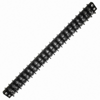
Barrier Blocks TERMINAL BLOCK QUICK REFERENCE Center-to- Number Single or Center of Double Screw Operating Series Spacing Terminals Row Size 140 .375 1-25 Double 5-40 141 .438 1-20 Double 6-32 142 .563 1-17 Double 8-32 150 .688 1-10 Double 10-32 ...
Page 5
... Dim. 1.032 1.407 1.782 2.157 2.532 2.907 3.282 3.657 4.032 4.407 4.782 5.157 5 ...
Page 6
... Catalog No. Y-140 3/4W-140 W-140 2-5 “W” Terminals Catalog No. 1-140-W 2-140-W 3-140-W 4-140-W 5-140-W ...
Page 7
... MS-9-140-Y MS-10-140 MS-10-140-Y MS-11-140 MS-11-140-Y MS-12-140 MS-12-140-Y MS-13-140 MS-13-140-Y MS-14-140 MS-14-140-Y MS-15-140 MS-15-140-Y MS-16-140 MS-16-140-Y MS-17-140 MS-17-140-Y MS-18-140 MS-18-140-Y MS-19-140 MS-19-140-Y MS-20-140 MS-20-140-Y MS-21-140 MS-21-140-Y MS-22-140 MS-22-140-Y MS-23-140 MS-23-140-Y MS-24-140 MS-24-140-Y MS-25-140 MS-25-140-Y 2-6 “Y” Terminal Marketed exclusively through distribution. ...
Page 8
Barrier Blocks Series 141 Electrical Characteristics Voltage Rating: 250 VAC RMS maximum Current Rating: 20 Amps maximum Maximum Watts Per Terminal: 5000 Mechanical Characteristics Maximum Wire Size: #14 AWG Recommended Tightening Torque: 12 lb.-in. Dimensions Ordering Information No. of Terminals ...
Page 9
Barrier Blocks Series 141 Solder Terminal Options Dimensions “Y” Terminals Ordering Information No. of Terminals Catalog No. 1 1-141-Y 2 2-141-Y 3 3-141-Y 4 4-141-Y 5 5-141-Y 6 6-141-Y 7 7-141-Y 8 8-141-Y 9 9-141-Y 10 10-141-Y 11 11-141-Y 12 ...
Page 10
... Use Standard Marker Strip for “3/4W” and “W” Solder Terminals. Accessories • Jumpers • Fanning Strips Call Toll Free: 1 (800) 323-9612 .438 Density, 6-32 x 1/4" BH Screw, Open Bottom, Double Row “Y” Terminal Catalog No. Catalog No. MS-1-141 MS-1-141-Y MS-2-141 MS-2-141-Y ...
Page 11
Barrier Blocks Series 142 Electrical Characteristics Voltage Rating: 250 VAC RMS maximum Current Rating: 30 Amps maximum Maximum Watts Per Terminal: 7500 Mechanical Characteristics Maximum Wire Size: #10 AWG Recommended Tightening Torque: 16 lb.-in. Dimensions Ordering Information No. of Terminals ...
Page 12
Barrier Blocks Series 142 Solder Terminal Options Dimensions “Y” Terminals Ordering Information No. of Terminals Catalog No 10-142-Y 11 11-142-Y 12 12-142-Y 13 13-142-Y 14 14-142-Y 15 15-142-Y 16 16-142-Y ...
Page 13
... Use Standard Marker Strips for “3/4W” and “W” Solder Terminals. Accessories • Jumpers • Fanning Strips Call Toll Free: 1 (800) 323-9612 .563 Density, 8-32 x 5/16" BH Screw, Open Bottom, Double Row Catalog No. Catalog No. MS-1-142 MS-1-142-Y MS-2-142 MS-2-142-Y MS-3-142 MS-3-142-Y MS-4-142 ...
Page 14
Density, 10-32 x 5/16" Barrier Blocks BH Screw, Open Bottom, Series 150 Double Row Electrical Characteristics Voltage Rating: 250 VAC RMS maximum Current Rating: 40 Amps maximum Maximum Watts Per Terminal: 10,000 Mechanical Characteristics Maximum Wire Size: #10 AWG ...
Page 15
Barrier Blocks Series 150 Marker Strips Dimensions Standard .688 TYP (17.46) Ordering Information No. of Terminals Accessories None Available for 150 Series. .688 Density, 10-32 x 5/16" BH Screw, Open ...
Page 16
Barrier Blocks Series 151 Electrical Characteristics Voltage Rating: 250 Volts maximum Current Rating: 50 Amps maximum Maximum Watts Per Terminal: 12,500 Mechanical Characteristics Maximum Wire Size: #8 Recommended Tightening Torque: 40 lb.-in. Dimensions Ordering Information No. of Terminals Catalog No. ...
Page 17
Barrier Blocks Series 152 Electrical Characteristics Voltage Rating: 250 Volts maximum Current Rating: 70 Amps maximum Maximum Watts Per Terminal: 54,000 Mechanical Characteristics Maximum Wire Size: #6 Recommended Tightening Torque: 75 lb.-in. Dimensions Ordering Information No. of Terminals Catalog No. ...
Page 18
Barrier Blocks Series 164 Electrical Characteristics Voltage Rating: 250 Volts maximum Current Rating: 15 Amps maximum Maximum Watts Per Terminal: 3750 Mechanical Characteristics Maximum Wire Size: #14 Recommended Tightening Torque: 12 lb.-in. Dimensions Ordering Information No. of Terminals 1 2 ...
Page 19
Barrier Blocks Series 164 Solder Terminal Options Dimensions “Y” Terminals Ordering Information No. of Terminals .375 Density, 6-32 x ...
Page 20
... MS-4-140 MS-4-140-Y MS-5-140 MS-5-140-Y MS-6-140 MS-6-140-Y MS-7-140 MS-7-140-Y MS-8-140 MS-8-140-Y MS-9-140 MS-9-140-Y MS-10-140 MS-10-140-Y MS-11-140 MS-11-140-Y MS-12-140 MS-12-140-Y MS-13-140 MS-13-140-Y MS-14-140 MS-14-140-Y MS-15-140 MS-15-140-Y MS-16-140 MS-16-140-Y MS-17-140 MS-17-140-Y MS-18-140 MS-18-140-Y MS-19-140 MS-19-140-Y MS-20-140 MS-20-140-Y MS-21-140 MS-21-140-Y 2-22 Marketed exclusively through distribution. ...
Page 21
... MSX-13-540 5.907 MSX-14-540 6.282 MSX-15-540 6.657 MSX-16-540 7.032 MSX-17-540 7.407 MSX-18-540 7.782 MSX-19-540 8.157 MSX-20-540 8.532 MSX-21-540 8.907 MSX-22-540 9.282 MSX-23-540 9.657 MSX-24-540 10.032 MSX-25-540 10.407 MSX-26-540 10.782 MSX-27-540 11.157 MSX-28-540 11.532 MSX-29-540 11.907 MSX-30-540 12.282 MSX-31-540 Marketed exclusively through distribution. ...
Page 22
... Marker Strip Catalog No. MSX-2-541 MSX-3-541 MSX-4-541 MSX-5-541 MSX-6-541 MSX-7-541 MSX-8-541 MSX-9-541 MSX-10-541 MSX-11-541 MSX-12-541 MSX-13-541 MSX-14-541 MSX-15-541 MSX-16-541 MSX-17-541 MSX-18-541 MSX-19-541 MSX-20-541 MSX-21-541 MSX-22-541 MSX-23-541 MSX-24-541 MSX-25-541 MSX-26-541 MSX-27-541 MSX-28-541 MSX-29-541 MSX-30-541 Marketed exclusively through distribution. Call Toll Free: 1 (800) 323-9612 ...
Page 23
... MSX-8-542 6.036 MSX-9-542 6.599 MSX-10-542 7.162 MSX-11-542 7.725 MSX-12-542 8.288 MSX-13-542 8.851 MSX-14-542 9.414 MSX-15-542 9.977 MSX-16-542 10.540 MSX-17-542 11.103 MSX-18-542 11.666 MSX-19-542 12.229 MSX-20-542 12.792 MSX-21-542 13.355 MSX-22-542 13.918 MSX-23-542 14.481 MSX-24-542 15.044 MSX-25-542 15.607 MSX-26-542 Marketed exclusively through distribution. ...
Page 24
Barrier Blocks Series 176 Electrical Characteristics Voltage Rating: 250 Volts maximum Current Rating: 15 Amps maximum Maximum Watts Per Terminal: 3750 Mechanical Characteristics Maximum Wire Size: 16 AWG Recommended Tightening Torque: 16 lb.-in. Dimensions L M Ordering Information With Mounting ...
Page 25
... Optional Terminals for use with Cinch terminal blocks. See chart for type and dimensions. (Below) 2 Ordering Information "3/4 W" Terminals - Dimensions Catalog A Number in mm 3/4W-140 .953 24.21 3/4W-141 1.156 29.36 3/4W-142 1.422 36.11 "Y" Terminals - Dimensions Catalog A Number in mm Y-140 .281 7.14 Y-141 .312 7.92 Y-142 ...
Page 26
... E 142J-2 540 C 540J 541 C 541J 542 C 542J * Connects two alternate terminals Screw Wire Gauge Size Range AWG 12 thru 22 10 thru 16 Type A Type D 2-29 QC-1 Shown Type B Type C Type F Type E Marketed exclusively through distribution. Call Toll Free: 1 (800) 323-9612 2 ...
Page 27
Barrier Block Accessories ■ Minimize wiring errors. ■ Available in straight and right-angle styles. ■ Available with cable clamp hole on right or left side, designated by “L” or “R” at end of catalog number. ■ Cable clamp hole for ...
Page 28
Barrier Block Accessories Catalog Numbers and Dimensions for Fanning Strips for 140 Series Terminal Blocks Straight Type Dimensions Catalog No. 6-160-R Ordering Information No. of Terminals Catalog No. 2 2-160-R 3 3-160-R 4 4-160-R 5 5-160-R 6 6-160-R 7 7-160-R ...
Page 29
DURA-CON ® Barrier Block High Reliability Accessories All-Plastic Catalog Numbers and Dimensions for Fanning Strips for 140 Series Terminal Blocks, Continued Right-Angle Type Dimensions 2 Ordering Information Call Toll Free: 1 (800) 323-9612 Fanning Strips Fanning Strips Catalog No. 6-160A-R ...
Page 30
Barrier Block Accessories Catalog Numbers and Dimensions for Fanning Strips for 141 Series Terminal Blocks Straight Type No. of Terminals Catalog No. Catalog No. 2 2-161-R 2-161-L 3 3-161-R 3-161-L 4 4-161-R 4-161-L 5 5-161-R 5-161-L 6 6-161-R 6-161-L 7 ...
Page 31
Barrier Block Accessories Catalog Numbers and Dimensions for Fanning Strips for 142 Series Barrier Blocks Straight Type Ordering Information No. of Terminals Catalog No. 2 2-162-R 3 3-162-R 4 4-162-R 5 5-162-R 6 6-162-R 7 7-162-R 8 8-162-R 9 9-162-R ...
Page 32
Barrier Block Accessories Materials Insulation Material rated XPC, chocolate Contact Material: Steel Contact Plating: Cadmium Mechanical Characteristics Mounting Hole: .140" (3.56mm) diameter Strip Dimension: .0625" (1.59mm) thick x .375" (9.53mm) wide Lug Density: .375" (9.53mm) Ordering Information ...
Page 33
Jones Plugs/Sockets Series 300 ■ Solder lug terminals with .093" x .062" (2.36mm x 1.57mm) wiring holes. ■ Two-contact "Jones" connector is round, all others are rectangular. ■ For use in cable-to-panel and cable-to-cable applications. ■ Designed for light and ...
Page 34
Jones Plugs/Sockets Series 300 Polarizing Patterns - 300 Series Multiple Density Solder Eyelet Marketed exclusively through distribution. Call Toll Free: 1 (800) 323-9612 2-37 ...
Page 35
Jones DURA-CON ® High Reliability Plugs/Sockets Series 300 All-Plastic Mounting Dimensions A Reference in mm 303 .453 11.51 304 .719 18.26 306 .719 18.26 2 308 .719 18.26 310 .719 18.26 312 .953 24.21 315-12 .953 24.21 315 1.016 25.81 ...
Page 36
Jones Plugs/Sockets Series 300 With Angle Bracket No. of Catalog No. Catalog No. Contacts Plug Socket 2 P-302-AB S-302-AB 3 P-303-AB S-303-AB 4 P-304-AB S-304-AB 6 P-306-AB S-306-AB 8 N/A N/A 10 P-310-AB N/A 12 P-312-AB N/A 15* N/A S-315-12-AB ...
Page 37
DURA-CON Jones ® Plugs/Sockets High Reliability All-Plastic Series 300 300 Series with Flush Plate (FP) No. of Catalog No. Contacts Plug 2 P-302-FP 3 P-303-FP 4 P-304- P-306-FP 8 N/A 10 P-310-FP 12 P-312-FP NOTE: Not available in ...
Page 38
Jones [.050” (1.27mm) Density Plugs/Sockets Solder Cup/Wire Series 300 D-Microminiature] 300 Series with End Brackets (EB) No. of Catalog No. Catalog No. Contacts Plug 15 P-315-EB 18 P-318-EB 21 P-321-EB 24 P-324-EB 28 P-328-EB 30 P-330-EB 33 P-333-EB NOTE: Not ...
Page 39
Jones DURA-CON ® Plugs/Sockets High Reliability Series 300 All-Plastic 300 Series with Recessed Plate (RP) No. of Catalog No. Contacts Plug 2 P-302-RP 3 P-303-RP 4 P-304-RP 6 P-306- N/A 10 P-310-RP 12 P-312-RP NOTE: Not available in ...
Page 40
... Polarizing in mm Pin 2.547 64.69 NO 2.859 72.62 NO 3.172 80.57 NO 3.484 88.49 14 3.797 96.44 14 4.109 104.38 14 4.422 112. 2.125 53.98 2.438 61.93 2.750 69.85 3.062 77.77 3.376 85.75 3.688 93.68 4.000 101.60 Marketed exclusively through distribution. Call Toll Free: 1 (800) 323-9612 2 ...
Page 41
DURA-CON Jones ® High Reliability Plugs/Sockets All-Plastic Series 300 300 Series Deep Bracket (DB) No. of Catalog No. Contacts Plug 2 P-302-DB 3 P-303-DB 4 P-304-DB 6 P-306- N/A 10 N/A 12 P-312-DB 15 P-315-DB 18 P-318-DB 21 ...
Page 42
... G Cable "D" Opening .313 7.95 .313 .344 8.74 .250 .453 11.51 .375 .469 11.91 .438 -- -- -- .359 9.12 .500 .422 10.72 .563 Cable Opening Polarizing in mm Pin .563 14.30 NO .563 14.30 NO .625 15.88 NO .625 15.88 14 .625 15.88 14 .750 19.05 14 .750 19 ...
Page 43
... E ± .031 “D” Cable Opening (.79mm .375 9.53 .359 9.12 .313 7.95 .359 9.12 .375 9 ...
Page 44
... Multiple Density Solder Eyelet 180° Clamp w/Locks N/A N/A N/A Plug B ± .016 C ± .031 (.41mm) (.79mm .953 24.21 11.99 .953 24.21 18 ...
Page 45
... SB CCE CCT CCT-L • • • * • • • • • • • • • • * • • • • • • • • • • • Marketed exclusively through distribution. CCT-K LAB • • • • • • • • ...
Page 46
Jones Plugs/Sockets Series 2400 ■ For use in cable-to-cable and cable-to-panel applications. ■ Designed for medium duty. ■ Plug prongs are .250" (6.35mm) wide and .055" (1.40mm) thick. ■ Socket contacts have solder eyelet contacts of .093" diameters. ■ Polarized ...
Page 47
Jones Plugs/Sockets Series 2400 2400 Series Less Angle Bracket No. of Catalog No. Catalog No. Contacts Plug 2 N/A S-2402-LAB 4 P-2404-LAB S-2404-LAB 6 P-2406-LAB S-2406-LAB 8 P-2408-LAB S-2408-LAB 10 P-2410-LAB S-2410-LAB 12 P-2412-LAB S-2412-LAB Plug Dimensions - Plug or ...
Page 48
DURA-CON Jones ® Plugs/Sockets High Reliability Series 2400 All-Plastic 2400 Series with Angle Bracket No. of Catalog No. Contacts Plug 2 N/A 4 P-2404-AB 6 P-2406-AB 8 P-2408-AB 10 P-2410- P-2412-AB Plug Dimensions - Plug or Socket No. ...
Page 49
Jones Plugs/Sockets Series 2400 2400 Series with Shallow Bracket No. of Catalog No. Contacts Plug 2 N/A 4 P-2404-SB 6 P-2406-SB 8 P-2408-SB 10 P-2410-SB 12 P-2412-SB Plug Socket Dimensions - Plug or Socket No Contacts in mm ...
Page 50
... N/A 4 P-2404-DB 6 P-2406-DB 8 P-2408- P-2410-DB 12 P-2412-DB Plug Dimensions - Plug or Socket No Contacts .922 23.42 4 1.359 34.53 6 1.797 45.64 8 2.234 56.74 10 2.672 67.87 12 3.109 78.97 Panel Cutout dimensions are on page 2-61. Call Toll Free: 1 (800) 323-9612 [.050” (1.27mm) Density Multiple Density Solder Cup/Wire ...
Page 51
Jones [.050” (1.27mm) Density Plugs/Sockets Solder Cup/Wire Series 2400 D-Microminiature] 2400 Series with Hood and 90° Clamp No. of Catalog No. Catalog No. Contacts Plug 2 N/A S-2402-CCE 4 P-2404-CCE S-2404-CCE 6 P-2406-CCE S-2406-CCE 8 P-2408-CCE S-2408-CCE 10 P-2410-CCE S-2410-CCE ...
Page 52
DURA-CON Jones ® Plugs/Sockets High Reliability Series 2400 All-Plastic 2400 Series with Hood and 180° Clamp No. of Catalog No. Contacts Plug 2 N/A 4 P-2404-CCT 6 P-2406-CCT 8 P-2408-CCT 2 10 P-2410-CCT 12 P-2412-CCT Plug Socket Dimensions - Plug ...
Page 53
... Panel Cutout Dimensions Shallow Bracket A Reference in mm P-2402-SB S-2402-SB 1.062 27.00 P-2404-SB S-2404-SB 1.500 38.10 P-2406-SB S-2406-SB 1.938 49.22 P-2408-SB S-2408-SB 2.376 60.34 P-2410-SB S-2410-SB 2.812 71.44 P-2412-SB S-2412-SB 3.250 82.56 Panel Cutout Dimensions Deep Bracket A Reference in mm P-2402-DB S-2402-DB 1 ...
Page 54
Circular Mini DIN Plugs ■ Contact positions and 8. ■ Pre-assembled with standard shielded cable lengths; consult factory for other lengths. ■ Molded-in strain relief. ■ Cable and overmold available in standard colors: black or ...
Page 55
... The above cable assemblies are recommended where greater contact durability is required. Additional Capabilities • Additional lengths or colors of the above cable assemblies can be produced. Consult factory for custom orders. • Custom-plated contacts can be provided. Consult factory for information. Single-Ended Cable Assembly 5-Contact ...
Page 56
Circular Mini DIN Plugs ■ Individual components available for cable assembly with overmolding. ■ Plug insulator available with contact positions and 8. ■ Seamless shield case is crimped to cable shield; designed to meet FCC ...
Page 57
... Prepare multi-conductor cable. • Crimp contacts onto individual conductors using tool MDT-P25 or tool MDT-P35. • Insert contact with conductor into insulator using tool MDT-P41 or have insertion tool MDT-P28 with insulator locating vice MDT-P29. • Insert insulator into the shield case using tool MDT-P34 or MDT-P30. ...
Page 58
... Dip solder tails on .200" (5.08mm) row centers double readout. ■ Bifurcated semi-bellows contacts for added contact reliability. ■ Ideal for applications involving vibration or board irregularities. ■ Contact positions: 12, 15, 18, 20, 22, 25, 28, 30, 31, 36, 37, 40, 43, 44, 49, 50, 52, 60, 70, AT, and XT. ■ Accepts .062" (1.59mm) thick PC boards. ...
Page 59
... 3.675 93.35 3.935 99.95 3.675 93.35 3.935 99.95 4.175 106.05 4.435 112.63 4.275 108.59 4.535 115.19 4.575 116.21 4.835 122.81 4.875 123.83 5.135 130.43 4.975 126.37 5.235 132.97 5.475 139.07 5.735 145.67 5.575 141.61 5.835 148.21 5.775 146.69 6.035 153.29 6.575 167 ...
Page 60
... Bifurcated semi-bellows contacts for added contact reliability. ■ Ideal for applications involving vibration or board irregularities. ■ Contact positions: 6, 10, 12, 15, 18, 22, 24, and 25. ■ Accepts single- or double-sided .062" (1.59mm) thick PC boards. ■ Available less mounting ears or with .128" (3.25mm) mounting hole. ...
Page 61
... Dip solder tails, double readout, .200" (5.08mm) row spacing, .156" (3.96mm) long 6/12 50-12SN-3 50-12SN-1 10/20 50-20SN-3 50-20SN-1 12/24 ...
Page 62
... Solder eyelet, single readout and double readout on .200" (5.08mm) row spacing. ■ Patented bifurcated bellows contacts for added contact reliability. ■ Ideal for applications involving vibration or board irregularities. ■ Contact positions: 6, 10, 12, 15, 18, 22, and 25. ■ Available with or without mounting ears. ■ Accepts single- or double-sided .062" (1.59mm) thick PC boards. ...
Page 63
... Single Readout Double Readout With Plain Mounting Holes Dimensions No Pos./Cont 1.100 27.94 10 1.724 43.79 12 2.036 51.71 15 2.504 63.60 18 2.972 75.49 20 3.286 83.46 22 3.596 91.34 25 4.067 103. 1.239 31.47 1.531 38.80 1.864 47.35 2.156 54.76 2.177 55.30 2.469 62.71 2.645 67.18 2.937 74 ...
Page 64
... Solder Eyelet Catalog No. 50-6H-20 50-10H-20 50-12H-20 50-15H-20 50-18H-20 50-20A-20 50-22H-20 50-25H-20 Less Mounting Ears Dip Solder Tails Dip Solder Tails .125" (3.18mm) Long .125" (3.18mm) Long Row Spacing Row Spacing Catalog No. Catalog No. 50-12H-30-2 50-12H-30-1 50-20H-30-2 50-20H-30-1 ...
Page 65
... Edge Connector High Reliability ■ Solder terminations, double readout. ■ Bifurcated bellows type contacts. ■ Contact positions: 6, 10, 12, 15, 18, 22, and 25. ■ Accepts .062" (1.59mm) thick double-sided PC boards. Insulation Material: Diallyl phthalate, green Contact Material: Beryllium copper Contact Plating: 30µin. select gold over 50µin. nickel in the contact areas, 10µ ...
Page 66
... Ordering Information No. of Pos./Cont. 6/12 10/20 12/24 15/30 18/36 22/44 25/50 .156" (3.96mm) Density Card Extender 1.239 31.47 1.531 38.88 1.864 47.34 2.156 54.76 2.177 55.29 2.469 62 ...
Page 67
Edge Connector Accessories Card Guides Card guide for .100" (2.54mm) and .156" (3.96mm) density edge connectors. Accepts .062" (1.59mm) thick PC boards. Card guides attach to mounting ears and guide printed circuit board into connector. Order separately. Material: Polypropylene Part ...
Page 68
... Call Toll Free: 1 (800) 323-9612 Plug Buttons Dimensions For Hole Diameter in mm .250 6.35 .375 9.53 .500 12.70 .625 15.88 .750 19.05 .875 22.23 1.000 25.40 1.250 31.75 1.000 25.40 2-74 Cup Diameter in mm Catalog No. .406 10.32 41A .500 12.70 41B ...
Page 69
Press-Fit BNC Coaxial Connector Board Mount Receptacle for 75 Ω Ω Applications ■ Solderless, Press-Fit Installation. ■ Strong, One-Piece Cast Body. ■ Standard BNC Interface. ■ 75Ω Ω Impedance. ■ Meets Lucent Technologies (AT&T) Requirements. Body: One-piece diecast zinc per ...
Page 70
Press-Fit BNC Coaxial Connector Board Mount Receptacle for 75 Ω Ω Applications Production Insertion Tool Design Press-Fit BNC Connector Dimensions Ordering Information Catalog Number: BNC-1-PF Standard Package: Anti-Static Tube, 48 Connectors Per Tube Call Toll Free: 1 (800) 323-9612 2-77 ...