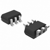
HSMP-389V-TR1G Avago Technologies US Inc., HSMP-389V-TR1G Datasheet - Page 3

HSMP-389V-TR1G
Manufacturer Part Number
HSMP-389V-TR1G
Description
DIODE PIN SWITCH 100V SOT-363
Manufacturer
Avago Technologies US Inc.
Type
Switchr
Datasheet
1.HSMP-3890-BLKG.pdf
(13 pages)
Specifications of HSMP-389V-TR1G
Diode Type
PIN - 2 Independant
Voltage - Peak Reverse (max)
100V
Current - Max
1A
Capacitance @ Vr, F
0.3pF @ 5V, 1MHz
Resistance @ If, F
2.5 Ohm @ 5mA, 100MHz
Package / Case
SC-70-6, SC-88, SOT-363
Diode Case Style
SOT-363
No. Of Pins
6
Capacitance Ct
0.2pF
Pin Configuration
Series Pair
Termination Type
SMD
Mounting Type
Surface Mount
Breakdown Voltage
100V
Operating Temperature Classification
Military
Reverse Voltage
100V
Mounting
Surface Mount
Operating Temperature (max)
150C
Operating Temperature (min)
-65C
Filter Terminals
SMD
Rohs Compliant
Yes
Capacitance
0.2pF
Forward Test Current If
1A
Lead Free Status / RoHS Status
Lead free / RoHS Compliant
Power Dissipation (max)
-
Lead Free Status / Rohs Status
Compliant
Available stocks
Company
Part Number
Manufacturer
Quantity
Price
Company:
Part Number:
HSMP-389V-TR1G
Manufacturer:
AVAGO
Quantity:
166 000
Company:
Part Number:
HSMP-389V-TR1G
Manufacturer:
Avago
Quantity:
180
Part Number:
HSMP-389V-TR1G
Manufacturer:
AVAGO/安华高
Quantity:
20 000
Electrical Specifications, T
T est Conditions
Notes:
1. Package marking code is white.
2. Package is laser marked.
High Frequency (Low Inductance, 500 MHz – 3 GHz) PIN Diodes
T est Conditions
Note:
1. SOT-23 package marking code is white; SOT-323 is laser marked.
Typical Parameters at
3
Part Number
Number
HSMP-
489x
Part
HSMP-
389B
389C
389R
389U
389V
3890
3892
3893
3894
3895
389E
389F
389L
389T
Test Conditions
Part Number
HSMP-
389x
Package
Marking
Code
GA
Package
Marking
[1]
Code
G0
G5
G0
GU
GV
G2
G3
G4
G2
G3
G4
GL
T
S
Z
C
[2]
[2]
[2]
= 25°C
[1]
[1]
[1]
[1]
[1]
[2]
[2]
[2]
[2]
[2]
[2]
C
Configuration
Dual Anode
= 25°C, each diode
Lead
Code
U
0
2
3
4
5
B
C
R
V
E
F
L
T
Configuration
Single
Series
Common Anode
Common Cathode
Unconnected Pair
Single
Series
Common Anode
Common Cathode
Unconnected Trio
Dual Switch Mode
Low Inductance Single
Series-Shunt Pair
High Frequency Series Pair
Series Resistance
f = 100 MHz
I
F
= 1 mA
R
Breakdown
3.8
S
Minimum
Measure
I
(ý)
Voltage
V
R
V
10 µA
R
100
BR
= V
(V)
BR
Resistance
Maximum
I
F
= 5 mA
Series
R
2.5
S
(ý)
Voltage V
Breakdown
Minimum
Measure
I
V
R
Carrier Lifetime
10 µA
R
100
= V
I
F
I
= 10 mA
R
= 6 mA
τ (ns)
200
BR
BR
(V)
Capacitance
f = 1 MHz
V
Typical
C
R
Total
0.33
T
= 5 V
(pF)
Series Resistance
f = 100 MHz
Maximum
I
F
= 5 mA
R
2.5
S
(ý)
Capacitance
Maximum
f = 1 MHz
V
C
0.375
R
Total
T
= 5 V
(pF)
Total Capacitance
0.20 @ 5V
C
Total Capacitance
T
(pF)
Maximum
f = 1 MHz
V
f=500 MHz–
C
R
Inductance
0.30
T
= 5 V
(pF)
Typical
L
3 GHz
Total
T
1.0
(nH)


