FFS.00.250.CTCE31 LEMO, FFS.00.250.CTCE31 Datasheet - Page 10
FFS.00.250.CTCE31
Manufacturer Part Number
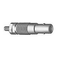
FFS.00.250.CTCE31
Description
PLUG COAX(50 ) CRIMP
Manufacturer
LEMO
Series
00 Seriesr
Datasheet
1.GCA.00.255.LT.pdf
(64 pages)
Specifications of FFS.00.250.CTCE31
Product Type
Connectors
Shell Style
Plug
Termination Style
Solder
Shell Plating
Chrome
Lead Free Status / Rohs Status
Lead free / RoHS Compliant


Technical Characteristics
Mechanical and climatical
Note :
Voltage Standing Wave Ratio
The VSWR (Voltage Standing Wave Ratio) is the value
representing the power reflected in a connection. The
VSWR varies with frequency, in most cases, the working
frequency range is where VSWR is ≤ 1.25.
Note : value for connectors with PTFE insulator. VSWR measured
50 Ω with a RG-174 A/U cable and 75 Ω with a RG-179 B/U cable.
Measured according to IEC-60169-1-1.
8
Contact retention force
Cable pull off force
Connector pull off force
Endurance
Operating temperature
1
VSWR
1.3
1.2
1.1
1.0
®
Characteristics
1)
depending on cable design
®
1)
S 4.5
500
~18
> 18 N
> 100 N
> 90 N
> 5000
cycles
Value
~26
FFS + PCS
- 55°C + 260°C
IEC 60512-8
IEC 60512-9
IEC 60512-8
IEC 60512-5
Standard
1000
Test
15a
17c
15f
1500
9a
f
Electrical
Shielding efficiency (EMC properties) in dB
(transfer impedance in dBohm)
The shielding efficiency is the ratio between the electro-
magnetic field inside the connector and a power source
at the outside of the connector (or vice versa).
Note : measured according to IEC-60169-1-3 standard.
FFA
Metal housing models
M1 Cable assembly, solder contact (page 39)
Impedance
Operating voltage (50 Hz)
Test voltage (50 Hz)
Rated current
Contact resistance
Shell electrical continuity
Insulating resistance
VSWR
Shielding efficiency
2
FFA.00.250.NTAC15
FFA.00.250.NTAC17
FFA.00.250.NTAC22
FFA.00.250.NTAC27
FFA.00.250.NTAC29
FFA.00.250.NTAC31
Part number
Characteristics
Straight plug with cable collet
-10
-20
-30
-40
0.01
FFA + PCA
0.1
Cable
group
2-3
9
–
1
4
8
50 Ω
0.7 kV rms
2.1 kV rms IEC 60512-2
4 A
< 6 mΩ
< 3.5 mΩ
> 10
see chart N°1 below
see chart N°2 below
1
Value
12
Ø max.
Cond.
FFS + PCS
Ω
0.55
0.55
0.55
0.55
0.55
0.55
10
IEC 60512-3
IEC 60512-2
IEC 60512-2
IEC 60512-2
Dielectric Ø
Standard
max.
1.45
1.45
1.95
1.95
1.95
1.95
100
–
–
FFV + PCS
1000 f
www.lemo.com
min.
1.1
1.3
1.7
2.2
2.4
2.6
(MHz)
Sheath Ø
(dB)
100
120
60
80
Test
4a
5a
2a
3a
2f
max.
1.4
1.6
2.1
2.6
2.8
3.0
Related parts for FFS.00.250.CTCE31
Image
Part Number
Description
Manufacturer
Datasheet
Request
R

Part Number:
Description:
RF Connectors ADAPTOR SOCKET TO BNC PLUG
Manufacturer:
LEMO
Datasheet:

Part Number:
Description:
RF Connectors ADAPT-BNC(UG88U)COAX
Manufacturer:
LEMO
Datasheet:
Part Number:
Description:
RF Connectors BNC ADAPTER 50 OHM
Manufacturer:
LEMO
Datasheet:

Part Number:
Description:
LEMO, SPRING LOADED DUSTCAP
Manufacturer:
LEMO
Datasheet:

Part Number:
Description:
Circular Push Pull Connectors CONNECTOR WRENCH FOR LEMO
Manufacturer:
LEMO


Part Number:
Description:
Basic / Snap Action / Limit Switches 1NC/1NO 230Vac 2A Non-Contact Switch
Manufacturer:
Honeywell
Part Number:
Description:
Basic / Snap Action / Limit Switches 2NC Safety 230Vac 2A Non-Contact Switch
Manufacturer:
Honeywell
Part Number:
Description:
Basic / Snap Action / Limit Switches 1NC/1NO 230Vac 2A Non-Contact Switch
Manufacturer:
Honeywell
Part Number:
Description:
Basic / Snap Action / Limit Switches 1NC/1NO 230Vac 2A Non-Contact Switch
Manufacturer:
Honeywell
Part Number:
Description:
Basic / Snap Action / Limit Switches 1NC/1NO 230Vac 2A Non-Contact Switch
Manufacturer:
Honeywell
Part Number:
Description:
Basic / Snap Action / Limit Switches 2NC Safety 230Vac 2A Non-Contact Switch
Manufacturer:
Honeywell
Datasheet:
Part Number:
Description:
Fused Coupler, Near Infrared
Manufacturer:
JDSU [JDS Uniphase Corporation]
Datasheet:
Part Number:
Description:
Fused Coupler, Visible Light
Manufacturer:
JDSU [JDS Uniphase Corporation]
Datasheet:
Part Number:
Description:
Specifications: Connector Type: Plug, Male Pins ; Shell Size - Insert: 114 ; Mounting Type: Free Hanging (In-Line) ; Fastening Type: Threaded ; Features: Shielded ; Packaging: Bulk ; Number of Positions: 114 ; Termination: Crimp ; Shell Material, Fin
Manufacturer:
LEMO