S6055R Littelfuse / Teccor Brand Thyristors, S6055R Datasheet
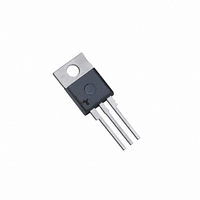
SCR NON-ISOLATE 600V 55A TO220AB

S6055R

Manufacturer Part Number
S6055R
Description
SCR NON-ISOLATE 600V 55A TO220AB
Manufacturer
Littelfuse / Teccor Brand Thyristors
Datasheets

Specifications of S6055R

Scr Type
Standard Recovery
Voltage - Off State
600V
Voltage - Gate Trigger (vgt) (max)
1.5V
Voltage - On State (vtm) (max)
1.8V
Current - On State (it (av)) (max)
35A
Current - On State (it (rms)) (max)
55A
Current - Gate Trigger (igt) (max)
40mA
Current - Hold (ih) (max)
60mA
Current - Off State (max)
10µA
Current - Non Rep. Surge 50, 60hz (itsm)
550A, 650A
Operating Temperature
-40°C ~ 125°C
Mounting Type
Through Hole
Package / Case
TO-220-3, TO-220AB
Current - On State (it (rms) (max)
55A
Lead Free Status / RoHS Status
Lead free / RoHS Compliant

Available stocks

Company
Part Number
Manufacturer
Quantity
Price
Part Number:
S6055R
Manufacturer:
SIEMENS
Quantity:
4 000
Part Number:
S6055R
Manufacturer:
TCE
Quantity:
1 000
Part Number:
S6055R
Manufacturer:
TOS
Quantity:
41
Sxx55x Series
Main Features
Absolute Maximum Ratings
I
V
I
I
I
I
I
di/dt
I
P
T
T
T(RMS)
GT
T(RMS)
T(AV)
TSM
2
GM
DRM
t
G(AV)
stg
J
Symbol
/V
Symbol
RRM
Sxx55x Series
Operating junction temperature range
Critical rate of rise of on-state current
Peak non-repetitive surge current
Average gate power dissipation
Storage temperature range
400 to 1000
Average on-state current
RMS on-state current
Value
I
Peak gate current
2
t Value for fusing
55
40
Parameter
Teccor
Revised: December 9, 2010 02:31 PM
®
55 Amp Standard SCRs
brand Thyristors
Unit
mA
A
V
295
single half cycle; f = 50Hz;
single half cycle; f = 60Hz;
Description
Excellent unidirectional switches for phase control
applications such as heating and motor speed controls.
Standard phase control SCRs are triggered with few
milliamperes of current at less than 1.5V potential.
Features & Benefits
Applications
Typical applications are AC solid-state switches, industrial
power tools, exercise equipment, white goods and
commercial appliances.
Schematic Symbol
f = 60Hz ; T
junctions
Test Conditions
T
T
J
J
A
(initial) = 25°C
(initial) = 25°C
t
T
T
T
P
T
p
C
C
J
J
W
= 8.3 ms
= 125°C
= 125°C
Please refer to http://www.littelfuse.com for current information.
= 90°C
= 90°C
= 10μS
J
= 125°C
Specifications are subject to change without notice.
-40 to 150
-40 to 125
to 1000 V
650 A
Value
1750
35.0
550
650
175
4.0
0.8
55
G
©2010 Littelfuse, Inc
K
Unit
A/μs
A
W
°C
°C
A
A
A
A
2
s

Related parts for S6055R

S6055R Summary of contents

Page 1

Sxx55x Series Main Features Symbol Value I 55 T(RMS 400 to 1000 DRM RRM Absolute Maximum Ratings Symbol Parameter I RMS on-state current T(RMS) I Average on-state current T(AV) I Peak non-repetitive surge current TSM ...

Page 2

Electrical Characteristics (T = 25°C, unless otherwise specified) J Symbol 12V DRM dv/ DRM DRM I ...

Page 3

Figure 1: Normalized DC Gate Trigger Current vs. Junction Temperature 2.0 1.5 1.0 0.5 0.0 -40 - Junction Temperature (T Figure 3: Normalized DC Holding Current vs. Junction Temperature 2.0 1.5 1.0 0.5 0.0 -40 - ...

Page 4

Figure 7: Maximum Allowable Case Temperature vs. Average On-State Current 130 The "R" or "M" package rating is intended for high surge condition use only and not recommended 125 for >32A (AV) continuous current use since narrow pin leads depending ...

Page 5

Figure 12: Surge Peak On-State Current vs. Number of Cycles 1000 100 Surge Current Duration -- Full Cycles Soldering Parameters Reflow Condition - Temperature Min (T Pre Heat - Temperature Max (T - Time (min to max) ...

Page 6

Physical Specifications Terminal Finish 100% Matte Tin-plated UL recognized epoxy meeting flammability Body Material classification 94V-0 Lead Material Copper Alloy Design Considerations Careful selection of the correct device for the application’s operating parameters and environment will go a long way ...

Page 7

Dimensions – TO-263AB (N-package) — MEASURING POINT ANODE GATE CATHODE 11.68 2.16 .460 .085 7.01 7.01 .276 .276 16.89 .665 8.89 1.40 .350 .055 3.81 .150 2.03 .080 ...

Page 8

Dimensions – TO-218AC (M Package) — Non-isolated Mounting Tab Common with Center Lead T c Measurement Point B U (diameter GATE P CATHODE M ANODE Product Selector Part Number 400V Sxx55R X ...

Page 9

... N: TO-263 (D - Pak) M: TO-218AC (Non-isolated) W: TO-218X (Non-isolated) 303 Revised: December 9, 2010 02:31 PM Gate Cathode Dimensions are in inches (and millimeters). S6055M S6055R Y M YMXXX ® ® ©2010 Littelfuse, Inc Specifications are subject to change without notice. Please refer to http://www.littelfuse.com for current information. ...

Related keywords