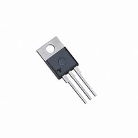
S8055R Littelfuse / Teccor Brand Thyristors, S8055R Datasheet - Page 3

S8055R
Manufacturer Part Number
S8055R
Description
SCR NON-ISOLATE 800V 55A TO220AB
Manufacturer
Littelfuse / Teccor Brand Thyristors
Specifications of S8055R
Scr Type
Standard Recovery
Voltage - Off State
800V
Voltage - Gate Trigger (vgt) (max)
1.5V
Voltage - On State (vtm) (max)
1.8V
Current - On State (it (av)) (max)
35A
Current - On State (it (rms)) (max)
55A
Current - Gate Trigger (igt) (max)
40mA
Current - Hold (ih) (max)
60mA
Current - Off State (max)
20µA
Current - Non Rep. Surge 50, 60hz (itsm)
550A, 650A
Operating Temperature
-40°C ~ 125°C
Mounting Type
Through Hole
Package / Case
TO-220-3, TO-220AB
Current - On State (it (rms) (max)
55A
Lead Free Status / RoHS Status
Lead free / RoHS Compliant
Available stocks
Company
Part Number
Manufacturer
Quantity
Price
Company:
Part Number:
S8055R
Manufacturer:
SIEMENS
Quantity:
5 000
Company:
Part Number:
S8055R
Manufacturer:
FSC
Quantity:
40 000
Part Number:
S8055R
Manufacturer:
TECCOR
Quantity:
20 000
Sxx55x Series
Note: xx = voltage
Figure 1: Normalized DC Gate Trigger Current
Figure 3: Normalized DC Holding Current
Figure 5: Power Dissipation (Typical)
2.0
1.5
1.0
0.5
0.0
2.0
1.5
1.0
0.5
0.0
-40
60
50
40
30
20
10
0
-40
0
vs. Junction Temperature
vs. Junction Temperature
vs. RMS On-State Current
5
-15
-15
10
RMS On-State Current [I
Junction Temperature (T
15
10
Junction Temperature (T
10
20
35
35
25
30
Teccor
60
T(RMS)
60
J
) -- (°C)
35
J
) -- (°C)
] - (Amps)
Revised: December 9, 2010 02:31 PM
40
85
85
®
55 Amp Standard SCRs
45
brand Thyristors
110
110
50
297
125
125
55
Figure 2: Normalized DC Gate Trigger Voltage
Figure 4: On-State Current vs. On-State Voltage
Figure 6: Maximum Allowable Case Temperature
2.0
1.5
1.0
0.5
0.0
130
125
120
115
110
105
100
120
100
95
90
85
80
75
70
-40
80
60
40
20
0
Please refer to http://www.littelfuse.com for current information.
0.7
0
vs. Junction Temperature
(Typical)
vs. RMS On-State Current
T
CURRENT WAVEFORM: Sinusoidal
LOAD: Resistive or Inductive
CONDUCTION ANGLE: 180°
J
5
= 25°C
0.8
-15
10
Specifications are subject to change without notice.
Instantaneous On-state Voltage (v
RMS On-State Current [I
0.9
15
Junction Temperature (T
10
1.0
20
25
35
1.1
The "R" or "M" package rating is intended
for high surge condition use only and not
recommended for >50A rms continuous
current use since narrow pin leads depend-
ing on lead length can exceed PCB solder
melting temperature. "W" package is
recommended for >50A rms continuous
current requirements.
30
1.2
T(RMS)
35
60
J
) -- (°C)
©2010 Littelfuse, Inc
] - Amps
1.3
40
T
) – Volts
85
45
1.4
50
1.5
110
55
125
1.6
60


