16TTS12FP Vishay, 16TTS12FP Datasheet - Page 3
16TTS12FP
Manufacturer Part Number
16TTS12FP
Description
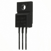
SCR PHASE CONT 1200V 16A TO220FP
Manufacturer
Vishay
Datasheet
1.16TTS08FP.pdf
(8 pages)
Specifications of 16TTS12FP
Scr Type
Standard Recovery
Voltage - Off State
1200V
Voltage - Gate Trigger (vgt) (max)
2V
Voltage - On State (vtm) (max)
1.4V
Current - On State (it (av)) (max)
10A
Current - On State (it (rms)) (max)
16A
Current - Gate Trigger (igt) (max)
60mA
Current - Hold (ih) (max)
100mA
Current - Off State (max)
10mA
Current - Non Rep. Surge 50, 60hz (itsm)
200A @ 50Hz
Operating Temperature
-40°C ~ 125°C
Mounting Type
Through Hole
Package / Case
TO-220-3 Full Pack (Straight Leads, Isolated), ITO-220AB
Current - On State (it (rms) (max)
16A
Breakover Current Ibo Max
200 A
Rated Repetitive Off-state Voltage Vdrm
1200 V
Off-state Leakage Current @ Vdrm Idrm
0.5 mA
Forward Voltage Drop
1.4 V
Gate Trigger Voltage (vgt)
2 V
Maximum Gate Peak Inverse Voltage
10 V
Gate Trigger Current (igt)
60 mA
Holding Current (ih Max)
100 mA
Mounting Style
Through Hole
Lead Free Status / RoHS Status
Contains lead / RoHS non-compliant
Other names
*16TTS12FP
VS-16TTS12FP
VS-16TTS12FP
VS16TTS12FP
VS16TTS12FP
VS-16TTS12FP
VS-16TTS12FP
VS16TTS12FP
VS16TTS12FP
Available stocks
Company
Part Number
Manufacturer
Quantity
Price
Company:

Part Number:
16TTS12FP
Manufacturer:
IR
Quantity:
12 500
Company:
Part Number:
16TTS12FPPBF
Manufacturer:
IR
Quantity:
2 000


Document Number: 93697
Switching
Thermal-Mechanical Specifications
Triggering
P
P
+ I
- V
I
V
V
I
t
t
t
T
T
R
R
R
wt
T
GT
GD
gt
rr
q
GM
GT
GD
G(AV)
J
stg
thJC
thJA
thCS
GM
GM
Typical turn-on time
Typical reverse recovery time
Typical turn-off time
Max. peak Gate Power
Max. average Gate Power
Max. paek positive Gate Current
Max. paek negative Gate Voltage
Max. required DC Gate Current
to trigger
Max. required DC Gate Voltage
to trigger
Max. DC Gate Voltage not to trigger
Max. DC Gate Current not to trigger
Parameters
Parameters
Max. Junction Temperature Range
Max. Storage Temperature Range
Max. Thermal Resistance Junction
to Case
Max. Thermal Resistance Junction
to Ambient
Typ. Thermal Resistance Case
to Heatsink
Approximate Weight
Mounting Torque
Case Style
Parameters
Min.
Max.
16TTS..FP Units
16TTS..FP Units
16TTS..FP Units
- 40 to 125
- 40 to 125
TO-220 FULLPAK
2 (0.07)
12 (10)
110
6 (5)
0.9
8.0
2.0
1.5
3.0
2.0
1.0
0.2
2.0
10
90
60
35
1.5
1.5
62
4
Kg-cm
(Ibf-in)
g (oz.)
°C/W
mA
mA
°C
W
A
V
V
µs
DC operation
Mounting surface, smooth and greased
(94/V0)
Anode supply = 6V, resistive load, T
Anode supply = 6V, resistive load, T
Anode supply = 6V, resistive load, T
Anode supply = 6V, resistive load, T
Anode supply = 6V, resistive load, T
Anode supply = 6V, resistive load, T
T
T
T
T
J
J
J
J
= 125°C, V
= 125°C, V
= 25°C
= 125°C
16TTS..FP
Preliminary Data Sheet I2147 rev. C 03/99
Conditions
Conditions
DRM
DRM
Conditions
= rated value
= rated value
www.vishay.com
IR
J
J
J
J
J
J
= 125°C
= 125°C
= - 10°C
= 25°C
= - 10°C
= 25°C
Series
3
Related parts for 16TTS12FP
Image
Part Number
Description
Manufacturer
Datasheet
Request
R

Part Number:
Description:
357-036-542-201 CARDEDGE 36POS DL .156 BLK LOPRO
Manufacturer:
Vishay
Datasheet:
Part Number:
Description:
357-036-542-201 CARDEDGE 36POS DL .156 BLK LOPRO
Manufacturer:
Vishay
Datasheet:
Part Number:
Description:
357-036-542-201 CARDEDGE 36POS DL .156 BLK LOPRO
Manufacturer:
Vishay
Datasheet:
Part Number:
Description:
357-036-542-201 CARDEDGE 36POS DL .156 BLK LOPRO
Manufacturer:
Vishay
Datasheet:
Part Number:
Description:
357-036-542-201 CARDEDGE 36POS DL .156 BLK LOPRO
Manufacturer:
Vishay
Datasheet:
Part Number:
Description:
357-036-542-201 CARDEDGE 36POS DL .156 BLK LOPRO
Manufacturer:
Vishay
Datasheet:
Part Number:
Description:
357-036-542-201 CARDEDGE 36POS DL .156 BLK LOPRO
Manufacturer:
Vishay
Datasheet:
Part Number:
Description:
357-036-542-201 CARDEDGE 36POS DL .156 BLK LOPRO
Manufacturer:
Vishay
Datasheet:
Part Number:
Description:
357-036-542-201 CARDEDGE 36POS DL .156 BLK LOPRO
Manufacturer:
Vishay
Datasheet:
Part Number:
Description:
357-036-542-201 CARDEDGE 36POS DL .156 BLK LOPRO
Manufacturer:
Vishay
Datasheet:
Part Number:
Description:
357-036-542-201 CARDEDGE 36POS DL .156 BLK LOPRO
Manufacturer:
Vishay
Datasheet:
Part Number:
Description:
357-036-542-201 CARDEDGE 36POS DL .156 BLK LOPRO
Manufacturer:
Vishay
Datasheet:
Part Number:
Description:
357-036-542-201 CARDEDGE 36POS DL .156 BLK LOPRO
Manufacturer:
Vishay
Datasheet:
Part Number:
Description:
357-036-542-201 CARDEDGE 36POS DL .156 BLK LOPRO
Manufacturer:
Vishay
Datasheet:
Part Number:
Description:
357-036-542-201 CARDEDGE 36POS DL .156 BLK LOPRO
Manufacturer:
Vishay
Datasheet: