ST203C12CFJ0 Vishay, ST203C12CFJ0 Datasheet - Page 2
ST203C12CFJ0
Manufacturer Part Number
ST203C12CFJ0
Description
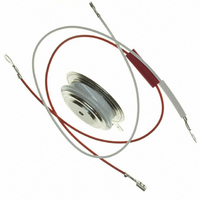
SCR PHASE CONT 1200V 370A A-PUK
Manufacturer
Vishay
Specifications of ST203C12CFJ0
Scr Type
Standard Recovery
Voltage - Off State
1200V
Voltage - Gate Trigger (vgt) (max)
3V
Voltage - On State (vtm) (max)
1.72V
Current - On State (it (av)) (max)
370A
Current - On State (it (rms)) (max)
700A
Current - Gate Trigger (igt) (max)
200mA
Current - Hold (ih) (max)
600mA
Current - Off State (max)
40mA
Current - Non Rep. Surge 50, 60hz (itsm)
5260A, 5510A
Operating Temperature
-40°C ~ 125°C
Mounting Type
Chassis Mount
Package / Case
TO-200AB, A-PUK
Current - On State (it (rms) (max)
700A
Mounting Style
SMD/SMT
Peak Repetitive Off-state Voltage, Vdrm
1.2kV
Gate Trigger Current Max, Igt
200mA
Current It Av
370A
On State Rms Current It(rms)
700A
Peak Non Rep Surge Current Itsm 50hz
5.26kA
Lead Free Status / RoHS Status
Lead free / RoHS Compliant
Other names
*ST203C12CFJ0


ST203CPbF Series
Vishay High Power Products
www.vishay.com
2
CURRENT CARRYING CAPABILITY
FREQUENCY
50 Hz
400 Hz
1000 Hz
2500 Hz
Recovery voltage V
Voltage before turn-on V
Rise of on-state current dI/dt
Heatsink temperature
Equivalent values for RC circuit
ON-STATE CONDUCTION
PARAMETER
Maximum average on-state current
at heatsink temperature
Maximum RMS on-state current
Maximum peak, one half cycle,
non-repetitive surge current
Maximum I
Maximum I
Maximum peak on-state voltage
Low level value of threshold voltage
High level value of threshold voltage
Low level value of forward slope resistance
High level value of forward slope resistance
Maximum holding current
Typical latching current
2
2
t for fusing
√t for fusing
r
d
For technical questions, contact: ind-modules@vishay.com
860
840
700
430
40
SYMBOL
180° el
V
V
I
I
T(RMS)
I
T(AV)
V
T(TO)1
T(TO)2
(Hockey PUK Version), 370 A
TSM
I
47/0.22
I
r
r
I
2
I
2
TM
t1
t2
H
L
V
√t
t
Inverter Grade Thyristors
50
DRM
50
750
706
580
340
55
I
TM
180° conduction, half sine wave
double side (single side) cooled
DC at 25 °C heatsink temperature double side cooled
t = 10 ms
t = 8.3 ms
t = 10 ms
t = 8.3 ms
t = 10 ms
t = 8.3 ms
t = 10 ms
t = 8.3 ms
t = 0.1 to 10 ms, no voltage reapplied
I
t
(16.7 % x π x I
(I > π x I
(16.7 % x π x I
(I > π x I
T
T
TM
p
J
J
= 10 ms sine wave pulse
= 25 °C, I
= 25 °C, V
= 600 A, T
T(AV)
T(AV)
1340
1400
1350
T
), T
), T
980
A
40
> 30 A
No voltage
reapplied
100 % V
reapplied
No voltage
reapplied
100 % V
reapplied
J
T(AV)
T(AV)
= 12 V, R
= T
J
J
180° el
TEST CONDITIONS
= T
= T
47/0.22
J
V
< I < π x I
< I < π x I
maximum,
50
DRM
J
J
-
maximum
maximum
RRM
RRM
a
= 6 Ω, I
1160
1220
1170
830
I
55
TM
T(AV)
T(AV)
Sinusoidal half wave,
initial T
), T
), T
G
= 1 A
J
J
J
= T
= T
= T
5620
2940
1750
J
J
J
910
40
maximum
maximum
maximum
100 µs
47/0.22
V
50
DRM
-
Document Number: 94370
5020
2590
1520
780
I
55
TM
370 (140)
VALUES
55 (85)
Revision: 30-Apr-08
5260
5510
4420
4630
1380
1000
1.72
1.17
1.22
0.92
0.83
700
138
126
600
98
89
UNITS
Ω/µF
A/µs
°C
UNITS
A
V
kA
kA
mΩ
mA
°C
A
A
V
2
2
√s
s
Related parts for ST203C12CFJ0
Image
Part Number
Description
Manufacturer
Datasheet
Request
R

Part Number:
Description:
357-036-542-201 CARDEDGE 36POS DL .156 BLK LOPRO
Manufacturer:
Vishay
Datasheet:
Part Number:
Description:
357-036-542-201 CARDEDGE 36POS DL .156 BLK LOPRO
Manufacturer:
Vishay
Datasheet:
Part Number:
Description:
357-036-542-201 CARDEDGE 36POS DL .156 BLK LOPRO
Manufacturer:
Vishay
Datasheet:
Part Number:
Description:
357-036-542-201 CARDEDGE 36POS DL .156 BLK LOPRO
Manufacturer:
Vishay
Datasheet:
Part Number:
Description:
357-036-542-201 CARDEDGE 36POS DL .156 BLK LOPRO
Manufacturer:
Vishay
Datasheet:
Part Number:
Description:
357-036-542-201 CARDEDGE 36POS DL .156 BLK LOPRO
Manufacturer:
Vishay
Datasheet:
Part Number:
Description:
357-036-542-201 CARDEDGE 36POS DL .156 BLK LOPRO
Manufacturer:
Vishay
Datasheet:
Part Number:
Description:
357-036-542-201 CARDEDGE 36POS DL .156 BLK LOPRO
Manufacturer:
Vishay
Datasheet:
Part Number:
Description:
357-036-542-201 CARDEDGE 36POS DL .156 BLK LOPRO
Manufacturer:
Vishay
Datasheet:
Part Number:
Description:
357-036-542-201 CARDEDGE 36POS DL .156 BLK LOPRO
Manufacturer:
Vishay
Datasheet:
Part Number:
Description:
357-036-542-201 CARDEDGE 36POS DL .156 BLK LOPRO
Manufacturer:
Vishay
Datasheet:
Part Number:
Description:
357-036-542-201 CARDEDGE 36POS DL .156 BLK LOPRO
Manufacturer:
Vishay
Datasheet:
Part Number:
Description:
357-036-542-201 CARDEDGE 36POS DL .156 BLK LOPRO
Manufacturer:
Vishay
Datasheet:
Part Number:
Description:
357-036-542-201 CARDEDGE 36POS DL .156 BLK LOPRO
Manufacturer:
Vishay
Datasheet:
Part Number:
Description:
357-036-542-201 CARDEDGE 36POS DL .156 BLK LOPRO
Manufacturer:
Vishay
Datasheet: