TIP32C-BP Micro Commercial Components (MCC), TIP32C-BP Datasheet
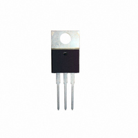
TIP32C-BP
Specifications of TIP32C-BP


Related parts for TIP32C-BP


TIP32C-BP Summary of contents
Page 1
... TIP32B TIP32C Collector-emitter Saturation Voltage V CE(sat =-3A I =-0.375A ) C B Base-emitter Voltage =- =- Collector cut-off current CES TIP32 (V =-40V TIP32A (V =-60V TIP32B (V =-80V TIP32C (V =-100V Collector cut-off current CEO TIP32/32A (-V =30V TIP32B/C (-V =60V Emitter cut-off current EBO (-V =5V current gain Hfe (I =- =-4V =- =-4V) ...
Page 2
... MCC's products are not authorized for use as critical components in life support devices or systems without the express written Counterfeiting of semiconductor parts is a growing problem in the industry. Micro Commercial Components (MCC) is taking strong measures to protect ourselves and our customers from the proliferation of counterfeit parts. MCC strongly encourages customers to purchase MCC parts either directly from MCC or from Authorized MCC Distributors who are listed by country on our web page cited below ...