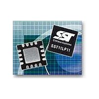
SST11LP11-QVCE Microchip Technology, SST11LP11-QVCE Datasheet - Page 4

SST11LP11-QVCE
Manufacturer Part Number
SST11LP11-QVCE
Description
RF Amplifier 4.9-5.8GHz 3.3V 500mA ICC 802.11a
Manufacturer
Microchip Technology
Type
Power Amplifierr
Datasheet
1.SST11LP11-QVCE.pdf
(14 pages)
Specifications of SST11LP11-QVCE
Operating Frequency
5800 MHz
Supply Current
260 mA
Maximum Operating Temperature
+ 85 C
Mounting Style
SMD/SMT
Minimum Operating Temperature
- 40 C
Number Of Channels
1 Channel
Lead Free Status / RoHS Status
Lead free / RoHS Compliant
EOL Data Sheet
ELECTRICAL SPECIFICATIONS
The AC and DC specifications for the power amplifier interface signals. Refer to Table 2 for the DC voltage and current spec-
ifications. Refer to Figures 3 through 12 for the RF performance.
Absolute Maximum Stress Ratings (Applied conditions greater than those listed under “Absolute Maximum
Stress Ratings” may cause permanent damage to the device. This is a stress rating only and functional operation
of the device at these conditions or conditions greater than those defined in the operational sections of this data
sheet is not implied. Exposure to absolute maximum stress rating conditions may affect device reliability.)
Supply Voltage to pins 4, 14, 15, 16 (V
DC supply current (I
Operating Temperature (T
Storage Temperature (T
Maximum Junction Temperature (T
Surface Mount Solder Reflow Temperature: . . . . . . . . . . . . . . . . . . . . . . . . . “with-Pb” units
Operating Range
TABLE 2: DC Electrical Characteristics
TABLE 3: AC Electrical Characteristics for Configuration
©2005 Silicon Storage Technology, Inc.
. . . . . . . . . . . . . . . . . . . . . . . . . . . . . . . . . . . . . . . . . . . . . . . . . . . . . . . . . . . . . . “non-Pb” units: 260°C for 3 seconds
Range
Industrial
V
I
Det
Det_ref
I
I
VREG1,2,3
Symbol
F
P
G
S
G
2f, 3f, 4f, 5f
CC
CQ
OFF
L-U
CC
OUT
VAR1
1. Certain “with-Pb” package types are capable of 260°C for 3 seconds; please consult the factory for the latest information.
Symbol
Parameter
Frequency range
Output power @ P
Small signal gain
Power detector sensitivity
Gain variation over band (4900~5855 MHz)
Harmonics at 21 dBm
Supply Voltage at pins 4, 14, 15, 16
Supply Current @ P
Power detector output voltage
Power detector output reference
Idle current
Shut down current
Reference Voltages for typical applications
Ambient Temp
-40°C to +85°C
CC
) . . . . . . . . . . . . . . . . . . . . . . . . . . . . . . . . . . . . . . . . . . . . . . . . . . . . . . . . . . . . . . . . . 500 mA
STG
A
) . . . . . . . . . . . . . . . . . . . . . . . . . . . . . . . . . . . . . . . . . . . . . . . . . . . . . . . . -40ºC to +85ºC
) . . . . . . . . . . . . . . . . . . . . . . . . . . . . . . . . . . . . . . . . . . . . . . . . . . . . . . -40ºC to +120ºC
IN
OUT
= -6 dBm for OFDM signal
J
Parameter
) . . . . . . . . . . . . . . . . . . . . . . . . . . . . . . . . . . . . . . . . . . . . . . . . . . . . . . . +150ºC
=21 dBm V
CC
) . . . . . . . . . . . . . . . . . . . . . . . . . . . . . . . . . . . . . . . . . . . . . . -0.3V to +5.5V
3.3V
V
CC
CC
=3.3V
4.9-5.8 GHz High-Linearity Power Amplifier
4
Min.
2.7
0.6
Min.
4.9
Typ
2.90
3.3
0.6
80
Max.
<1.0
260
4.2
2.2
0.04
1.75
Typ
-40
18
24
Unit
mA
mA
µA
V
V
V
V
1
: 240°C for 3 seconds
Max.
5.8
802.11a modulation
Test Conditions
-10 to +22 dBm
S71284-03-EOL
SST11LP11
V/dB
dBm
Unit
GHz
dBc
dB
dB
T2.0 1284
T3.0 1284
07/09


