CA3-B0-34-620-121-C Carling Technologies, CA3-B0-34-620-121-C Datasheet - Page 5
CA3-B0-34-620-121-C
Manufacturer Part Number
CA3-B0-34-620-121-C
Description
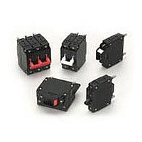
Circuit Breakers 3 POLE 20 Amp
Manufacturer
Carling Technologies
Type
Hydraulic/Magneticr
Specifications of CA3-B0-34-620-121-C
Product Type
Circuit Breakers
Actuator Type
Handle
Brand/series
C Series
Color, Actuator
Black
Current, Rating
20 A
Dimensions
2.475"Lx2.265"Wx2.5"H
Mounting Hole Size
0.156 "
Mounting Type
Panel
Number Of Poles
3
Standards
UL Listed, CSA Certified
Termination
Stud
Thread Length
0.625
Voltage, Rating
480 WYE/277 VAC
Lead Free Status / RoHS Status
Lead free / RoHS Compliant


78
C-Series – General Specifications
Electrical
Maximum Voltage
Current Rating
Standard Voltage Coils
Auxiliary Switch Rating
Insulation Resistance
Dielectric Strength
Resistance, Impedance
Pulse Tolerance Curves
AC, 480 WYE/277 VAC, 50/60 Hz
(see Table A.)
UL489: AC,240 VAC. (See Table D),
50/60 Hz, 125 VDC
Standard current coils: 0.100, 0.250,
0.500, 0.750, 1.00, 2.50, 5.00, 7.50,
10.0, 15.0, 25.0, 30.0, 35.0, 40.0,
50.0, 60.0, 70.0, 80.0, 90.0 and 100
amps. Other ratings available, see
Ordering Scheme.
DC - 6V, 12V; AC - 120V; other rat-
ings available, see Ordering
Scheme.
SPDT; 10.1 amps-250VAC, DC Aux.
Switch 1.0A, 65 VDC. 0.5A,
80VDC,1/4 HP, 125VAC,VDE & TUV
1.0 125 VAC.
Minimum of 100 Megohms at 500 VDC.
UL, CSA: 1960 V 50/60 Hz for one
minute between all electrically isolat-
ed terminals. C-Series Circuit
Breakers comply with the 8mm
spacing and 3750V 50/60 Hz dielec-
tric requirements from hazardous
voltage to operator accessible sur-
faces, between adjacent poles and
from main circuits to auxiliary circuits
per Publications EN 60950 and VDE
0805.
Values from Line to Load Terminal -
based on Series Trip Circuit Breaker.
Mechanical
Endurance
Trip Free
Trip Indication
Physical
Number of Poles
Internal Circuit Configurations Series (with or without auxiliary
Weight
Standard Colors
Designed and tested in accordance with requirements of specifi-
cation MIL-PRF-55629 & MIL-STD-202 as follows:
Shock
Vibration
Moisture Resistance
Salt Spray
Thermal Shock
Operating Temperature
Environmental
10,000 ON-OFF operations @ 6 per
minute; with rated current & voltage.
All C-Series circuit breakers will trip
on overload, even when actuator is
forcibly held in the ON position.
The operating actuator moves posi-
tively to the OFF position when an
overload causes the breaker to trip.
With mid-trip, handle moves to the
mid position on electrical trip of the
circuit breaker. With mid trip handle
with alarm switch, handle moves to
the mid position and the alarm
switch actuates when the circuit
breaker is electrically tripped.
1-6 poles ≤ 50A; 1-4 poles @ 51-
70A; 1-2 poles 71-100A. UL489
Handle: 1 pole ≤ 100A, 2 pole ≤
50A; Rocker: 1 pole ≤ 100A.
switch, mid trip & mid trip with alarm
switch) Shunt & Relay with current
or voltage trip coils, Dual Coil,
Switch Only (with or without aux.
switch). UL489: Series (with or with-
out auxiliary switch, mid-trip & mid-
trip with alarm switch).
Approx.112 grams/pole ( 3.95 oz).
Housing: Black
Withstands 100 Gs, 6ms sawtooth
while carrying rated current per
Method 213, Test Condition "I".
Instantaneous and ultrashort curves
tested @ 90% of rated current.
Withstands 0.060" excursion from 10-
55 Hz & 10 Gs 55-500 Hz, @ rated
current per Method 204C, Test Cond.
A. Instantaneous & ultrashort curves
tested @ 90% of rated current.
Method 106D, i.e., ten 24-hour
cycles @ +25°C to +65°C, 80-98%
RH.
Method 101, Condition A (90-95%
RH @ 5% NaCl Solution, 96 hrs).
Method 107D, Condition A (five cycles
@ -55°C to +25°C to +85°C to +25°C).
-40°C to +85°C
www.carlingtech.com
Related parts for CA3-B0-34-620-121-C
Image
Part Number
Description
Manufacturer
Datasheet
Request
R

Part Number:
Description:
Circuit Breakers 3 POLE 40 AMPS
Manufacturer:
Carling Technologies
Datasheet:
Part Number:
Description:
Circuit Breakers 3 POLE 50 AMPS
Manufacturer:
Carling Technologies
Datasheet:
Part Number:
Description:
Circuit Breakers 3 POLE 15 AMPS
Manufacturer:
Carling Technologies
Datasheet:
Part Number:
Description:
Circuit Breakers 3 POLE 5 AMPS
Manufacturer:
Carling Technologies
Datasheet:
Part Number:
Description:
Circuit Breakers 3 POLE 10 AMPS
Manufacturer:
Carling Technologies
Datasheet:
Part Number:
Description:
Circuit Breakers 3 PLOE 30 AMPS
Manufacturer:
Carling Technologies
Datasheet:
Part Number:
Description:
Circuit Breakers 3 POLE 20 A
Manufacturer:
Carling Technologies
Datasheet:

Part Number:
Description:
LIGHT INDICATOR GRN 12VDC PNLMNT
Manufacturer:
Carling Technologies
Part Number:
Description:
CONTURA ILL INDICATOR 12V RED
Manufacturer:
Carling Technologies
Part Number:
Description:
Current Regulator Diodes CURRENT REGULATOR DIODES 3.6mA
Manufacturer:
Carling Technologies
Part Number:
Description:
Rocker Switches
Manufacturer:
Carling Technologies
Datasheet: