MF-VS240-0 Bourns Inc., MF-VS240-0 Datasheet

PTC Resettable Fuses 16Volts 100Amps Hold 2.4A Trip 5.9

MF-VS240-0

Manufacturer Part Number
MF-VS240-0
Description
PTC Resettable Fuses 16Volts 100Amps Hold 2.4A Trip 5.9
Manufacturer
Bourns Inc.
Type
PTC Resettable Fusesr
Series
MF-VSr
Datasheet

Specifications of MF-VS240-0

Hold Current
2.4 Amps
Trip Current
5.9 Amps
Current Rating (max)
100 Amps
Resistance
0.026 Ohms
Maximum Voltage
16 VoltsDC
Termination Style
Axial
Mounting Style
Snap In
Current Rating
100 Amps
Dimensions
14.6 mm L x 0.9 mm W x 0.9 mm H
Operating Temperature Range
- 40 C to + 85 C
Lead Free Status / RoHS Status
Lead free / RoHS Compliant
*
Specifications are subject to change without notice.
Customers should verify actual device performance in their specific applications.
Operating/Storage Temperature ........................-40 °C to +85 °C
Maximum Device Surface Temperature
Passive Aging......................................................+60 °C, 1000 hours ....................................±10 % typical resistance change
Humidity Aging....................................................+60 °C, 85 % R.H.1000 hours ....................±10 % typical resistance change
Thermal Shock ....................................................MIL-STD-202F, Method 107G ....................±5 % typical resistance change
Vibration ..............................................................MIL-STD-883C, ..........................................No change
Test
Visual/Mech. ......................................................Verify dimensions and materials..................Per MF physical description
Resistance ..........................................................In still air @ 23 °C ........................................Rmin ≤ R ≤ R1max
Time to Trip ........................................................At specified current, Vmax, 23 °C ..............T ≤ max. time to trip (seconds)
Hold Current ......................................................30 min. at Ihold............................................No trip
Trip Cycle Life ....................................................Vmax, Imax, 100 cycles ..............................No arcing or burning
Trip Endurance....................................................Vmax, 48 hours ..........................................No arcing or burning
UL File Number ..................................................E 174545S
CSA File Number ................................................CA 110338
TÜV File Number ................................................R2057213
*I trip is approximately two times I hold.
RoHS Directive 2002/95/EC Jan 27 2003 including Annex
Thermal Derating Chart - I hold (Amps)
Electrical Characteristics
MF-VS170
MF-VS210
MF-VS170
MF-VS210
in Tripped State ................................................125 °C
Model
Model
Environmental Characteristics
Test Procedures And Requirements For Model MF-VS Series
V max.
Volts
16
16
-40 °C
3.2
4.1
Amps
I max.
100
100
-20 °C
2.7
3.5
I hold
Hold
1.7
2.1
Amperes
At 23 °C
Test Conditions
+85 °C to -40 °C, 10 times
Condition A
MF-VS Series -
Features
Axial leaded
Fully compatible with current
industry standards
Weldable nickel terminals
Very low internal resistance
Low switching temperature
RoHS compliant*
0 °C
2.2
2.9
I trip
Trip
3.4
4.7
Ambient Operating Temperature
0.030
0.018
23 °C
Min.
1.7
2.1
Resistance
At 23 °C
0.052
0.030
Ohms
Initial
Max.
PTC Resettable Fuses
40 °C
1.3
1.6
0.040
0.022
Typ.
Accept/Reject Criteria
50 °C
1.1
1.3
1 Hour (R 1 )
Resistance
Post-Trip
At 23 °C
Ohms
0.105
0.060
Max.
Applications
Any application that requires protection
at low resistances
Rechargeable battery packs; designed for
NiMH and Li-Ion chemical characteristics
Cellular phones
Laptop computers
60 °C
Amperes Seconds
At 23 °C
0.8
1.0
10.0
8.5
Max. Time
To Trip
At 23 °C
70 °C
0.6
0.7
3.0
5.0
Dissipation
At 23 °C
Tripped
Watts
Power
85 °C
Typ.
1.4
1.5
0.1
0.1

Related parts for MF-VS240-0

MF-VS240-0 Summary of contents

Page 1

... Humidity Aging....................................................+60 ° R.H.1000 hours ....................±10 % typical resistance change Thermal Shock ....................................................MIL-STD-202F, Method 107G ....................±5 % typical resistance change Vibration ..............................................................MIL-STD-883C, ..........................................No change Test Procedures And Requirements For Model MF-VS Series Test Visual/Mech. ......................................................Verify dimensions and materials..................Per MF physical description Resistance ..........................................................In still air @ 23 °C ........................................Rmin ≤ R ≤ R1max Time to Trip ........................................................At specified current, Vmax, 23 ° ...

Page 2

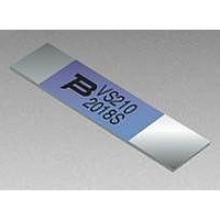
... Represents total content. Layout may vary. MANUFACTURER'S TRADEMARK F VS210 2018S DATE CODE D (FIRST DIGIT = LAST DIGIT OF YEAR; C NEXT THREE DIGITS = DAY OF YEAR) 10 Fault Current (Amps) MF-VS SERIES, REV. L, 02/08 Specifications are subject to change without notice. Pkg. Style 4.1 Std. 4.1 Std. 4.1 Std. 4.1 Std. 4 ...

Page 3

... MF-S, MF-LS, MF-LR and MF-VS Series Tape and Reel Specifications Taped Component Dimensions 1.0 + 0.1/ -0 (.039 + .004/-0) DIA. 5.56 ± 0.10 (.219 ± .004) Reel Dimensions 330 (13.0) 48.0 ± 0.3 (1.90 ± .012) 12.0 ± 0.1 (.472 ± .004) 4.0 ± 0.1 (.157 ± ...

Related keywords