PTFT0805 10K 5% Vishay, PTFT0805 10K 5% Datasheet

Thermistors - PTC 10Kohms 5%

PTFT0805 10K 5%

Manufacturer Part Number
PTFT0805 10K 5%
Description
Thermistors - PTC 10Kohms 5%
Manufacturer
Vishay
Type
PTCr
Datasheet

Specifications of PTFT0805 10K 5%

Resistance
10 KOhms
Tolerance
5 %
Termination Style
SMD/SMT
Operating Temperature Range
- 55 C to + 125 C
Dimensions
1.25 mm W x 2 mm L x 0.5 mm H
Voltage
40 V
Package / Case
0805
Lead Free Status / RoHS Status
Lead free / RoHS Compliant
PTFT
Vishay Dale
www.vishay.com
4
Notes 1. Contact Vishay Dale if closer TCR lot tolerance is desired.
Note 1. Rated Continuous Working Voltage is maximum working voltage or square root of the power rating times resistance value, whichever is less.
STANDARD ELECTRICAL SPECIFICATIONS
STANDARD RESISTANCE VALUES
STANDARD TECHNICAL SPECIFICATIONS
- 55
GLOBAL PART NUMBER INFORMATION
New Global Part Numbering: PTFT1206L1002KZ (preferred part numbering format)
Historical Part Number: PTFT1206L1002KZ (will continue to be accepted)
HISTORICAL MODEL
GLOBAL MODEL
°
TCR LOT
C to + 125
PTFT0603
PTFT0805
PTFT1206
3500
3300
3100
2900
2700
2500
2300
PTFT1206
ppm
PART NUMBER
P
PTFT 0603
PTFT 0805
PTFT 1206
°
C
100
10
12
15
18
22
27
33
39
47
56
68
82
Linear PTC Thermistors, Surface Mount Chip
T
TOLERANCE
F
TCR
± 300
± 300
± 300
± 300
± 300
± 300
± 300
CHARACTERISTIC
ppm
CHARACTERISTIC
T
L = Linear
1)
L
1
For technical questions, contact: thermistor1@vishay.com
2
MIN.
1.5K
6.8K
150
330
680
10
27
0
RESISTANCE VALUE
RESISTANCE VALUE
0603
6
POWER RATING
-
-
-
-
-
-
-
1002 = 10K
100 mW
125 mW
L
R
75 mW
1002
MAX.
1.2K
5.6K
1.2K
10K
25
120
270
560
120
150
180
220
270
330
390
470
560
680
820
1K
22
VALUE RANGE (5 % and 10 % TOLERANCE)
1
2. Other R
FEATURES
• Solderable wraparound terminations
• Alumina substrate base with PTC thick film element
• 0603, 0805, and 1206 sizes available
• Available in tape and reel packaging
• Standard tolerances: ± 5 %, ± 10 %
• Contact factory for non-standard tolerance
• Linear from - 55 °C to + 125 °C
• Maximum linear deviation: ± 0.01 %/°C
0
25
MIN.
1.8K
8.2K
220
390
820
10
47
TOLERANCE CODE
values and tolerances are available upon request.
0
TOLERANCE CODE
K = ± 10 %
J = ± 5 %
0805
2
-
-
-
-
-
-
-
K
MAXIMUM WORKING VOLTAGE RCWV
K
MAX.
1.5K
6.8K
10K
180
330
680
39
Z
W = Lead (Pb)-free, T/R (Full)
F = Lead (Pb)-free, Bulk
30 VDC
40 VDC
50 VDC
Z = Tin/Lead, T/R (Full)
MIN.
1.2K
4.7K
1.5K
1.8K
2.2K
2.7K
3.3K
3.9K
4.7K
5.6K
6.8K
8.2K
Document Number 33014
270
560
10K
10K
12K
15K
P = Tin/Lead, Bulk
10
56
PACKAGING
PACKAGING
2)
Revision 04-Apr-05
1206
Z
-
-
-
-
-
-
-
MAX.
3.9K
8.2K
220
470
15K
1K
47
1)

Related parts for PTFT0805 10K 5%

PTFT0805 10K 5% Summary of contents

Page 1

... C ppm 3500 ± 300 3300 ± 300 3100 ± 300 2900 ± 300 2700 ± 300 2500 ± 300 2300 ± 300 Notes 1. Contact Vishay Dale if closer TCR lot tolerance is desired. STANDARD RESISTANCE VALUES 100 STANDARD TECHNICAL SPECIFICATIONS PART NUMBER ...

Page 2

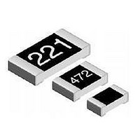
... Overglaze Thermistor Alumina Substrate Inner Electrode Nickel Barrier Solderable Coating For technical questions, contact: thermistor1@vishay.com Vishay Dale 0.012 ± 0.008 0.012 ± 0.008 [0.30 ± 0.20] [0.30 ± 0.20] 0.016 ± ...

Page 3

... Information contained herein is intended to provide a product description only. No license, express or implied, by estoppel or otherwise, to any intellectual property rights is granted by this document. Except as provided in Vishay's terms and conditions of sale for such products, Vishay assumes no liability whatsoever, and disclaims any express or implied warranty, relating to sale and/or use of Vishay products including liability or warranties relating to fitness for a particular purpose, merchantability, or infringement of any patent, copyright, or other intellectual property right ...

Related keywords