QM48T14120-NDB0G POWER ONE, QM48T14120-NDB0G Datasheet - Page 5
QM48T14120-NDB0G
Manufacturer Part Number
QM48T14120-NDB0G
Description
DC/DC Converters & Regulators
Manufacturer
POWER ONE
Type
Step Downr
Datasheet
1.QM48T14120-NDB0G.pdf
(20 pages)
Specifications of QM48T14120-NDB0G
Output Power
168W
Output Current
14A
Input Voltage
48V
Output Voltage
12V
Screening Level
Industrial
Product Length (mm)
36.83mm
Product Height (mm)
7.08mm
Product Depth (mm)
58.42mm
Mounting Style
Through Hole
Pin Count
8
Number Of Outputs
1
Package / Case
Quarter-Brick
Product
Isolated
Input Voltage Range
36 V to 75 V
Input Voltage (nominal)
48 V
Output Voltage (channel 1)
12 V
Output Current (channel 1)
14 A
Isolation Voltage
2000 V
Package / Case Size
Quarter Brick
Lead Free Status / RoHS Status
Compliant
Lead Free Status / RoHS Status
Compliant


equal to the product of the nominal output voltage
and the allowable output current for the given
conditions.
When using remote sense, the output voltage at the
converter can be increased by as much as 10%
above the nominal rating in order to maintain the
required voltage across the load. Therefore, the
designer must, if necessary, decrease the maximum
current (originally obtained from the derating curves)
by the same percentage to ensure the converter’s
actual output power remains at or below the
maximum allowable output power.
Output Voltage Adjust /TRIM (Pin 6)
The output voltage can be adjusted up 10% (V
40 V) or down 20% relative to the rated output
voltage by the addition of an externally connected
resistor.
The TRIM pin should be left open if trimming is not
being used. To minimize noise pickup, a 0.1 µF
capacitor is connected internally between the TRIM
and SENSE(-) pins.
To increase the output voltage, refer to Fig. C. A trim
resistor, R
TRIM (Pin 6) and SENSE(+) (Pin 7), with a value of:
for non-paralleling option
R
for paralleling option
where,
Vin
When trimming up, care must be taken not to exceed
the converter‘s maximum allowable output power.
ZD-00376 Rev. 1.1.1, 19-Feb-10
R
R
V
Δ
V
T-INCR
T
T
O
O
INCR
INCR
NOM
REQ
Fig. C: Configuration for increasing output voltage.
(V
= 45(100+)/(*N
O
5.11(100
-
REQ
Required value of trim-up resistor [kΩ]
Nominal value of output voltage [V]
Desired (trimmed) output voltage [V].
T-INCR
V
O
Vin (+)
ON/OFF
Vin (-)
-
NOM
V
, should be connected between the
O
1.225Δ
-
NOM
Δ)V
QmaX
(Top View)
)
Converter
O
X
P
NOM
TM
)
Series
100
626
SENSE (+)
SENSE (-)
Vout (+)
Vout (-)
TRIM
10.22
[%]
R
T-INCR
[kΩ],
QM48T/S14120 DC-DC Converter Data Sheet
[kΩ],
Rload
IN
Page 5 of 20
>
36-75 VDC Input; 12 VDC @ 14 A Output
[V
See the previous section for a complete discussion
of this requirement.
To decrease the output voltage (Fig. D), a trim
resistor, R
TRIM (Pin 6) and SENSE(-) (Pin 5), with a value of:
for non-paralleling option
R
for paralleling option
where,
and Δ is defined above.
Note:
The above equations for calculation of trim resistor values match
those typically used in conventional industry-standard quarter-
bricks.
TRIM/SENSE Function Notes:
This equation is applicable for any condition of output sensing
and/or output trim.
R
R
1. Trim/Sense Functions have limited capability for Vin < 40 V.
2. Trimming/sensing beyond 110% of the rated output voltage is
not an acceptable design practice, as this condition could cause
unwanted triggering of the output overvoltage protection (OVP)
circuit. The designer should ensure that the difference between
the voltages across the converter’s output pins and its sense pins
does not exceed 10% of V
Vin
OUT
T-DECR
T
T
DECR
DECR
) (
Fig. D: Configuration for decreasing output voltage.
= (511-5.6)/(*N
V
|
511
OUT
Δ
Required value of trim-down resistor [kΩ]
T-DECR
(
|
)]
Vin (+)
ON/OFF
Vin (-)
10.22
, should be connected between the
[V
SENSE
OUT
QmaX
QmaX
QmaX
(Top View)
) (
Converter
(
NOM
P
)
TM
TM
V
Series
), or:
SENSE
www.power-one.com
(
SENSE (+)
SENSE (-)
)]
Vout (+)
Vout (-)
TRIM
V
O
[kΩ],
[kΩ],
-
NOM
R
X
T-DECR
10%
Rload
[V]
Related parts for QM48T14120-NDB0G
Image
Part Number
Description
Manufacturer
Datasheet
Request
R

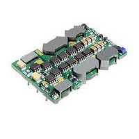
Part Number:
Description:
Module DC-DC 1-OUT 12V 14A 168W 8-Pin Quarter-Brick
Manufacturer:
POWER ONE
Datasheet:

Part Number:
Description:
SWITCHING POWER SUPPLIES, SINGLE OUTPUT, 80 WATTS
Manufacturer:
POWER ONE
Datasheet:
Part Number:
Description:
HAS SERIES - 30 WATT
Manufacturer:
POWER ONE
Datasheet:
Part Number:
Description:
SINGLE OUTPUT
Manufacturer:
POWER ONE
Datasheet:

Part Number:
Description:
BRS DC/DC converters(1.5 WATT)
Manufacturer:
Power-One
Datasheet:
Part Number:
Description:
3...15 Watt DC-DC Converter
Manufacturer:
Power-One
Datasheet:
Part Number:
Description:
HBS SERIES - 100 WATT
Manufacturer:
Power-One
Datasheet:
Part Number:
Description:
3...15 Watt DC-DC Converter
Manufacturer:
Power-One
Datasheet:
Part Number:
Description:
BUS DC/DC converters(3 WATT)
Manufacturer:
Power-One
Datasheet: