BCP69T1 ON Semiconductor, BCP69T1 Datasheet

TRANS PNP AUDIO 1A 20V SOT223

BCP69T1

Manufacturer Part Number
BCP69T1
Description
TRANS PNP AUDIO 1A 20V SOT223
Manufacturer
ON Semiconductor
Datasheet

Specifications of BCP69T1

Transistor Type
PNP
Current - Collector (ic) (max)
1A
Voltage - Collector Emitter Breakdown (max)
20V
Vce Saturation (max) @ Ib, Ic
500mV @ 100mA, 1A
Dc Current Gain (hfe) (min) @ Ic, Vce
85 @ 500mA, 1V
Power - Max
1.5W
Frequency - Transition
60MHz
Mounting Type
Surface Mount
Package / Case
SOT-223 (3 leads + Tab), SC-73, TO-261
Lead Free Status / RoHS Status
Contains lead / RoHS non-compliant
Current - Collector Cutoff (max)
-
Other names
BCP69T1OSCT

Available stocks

Company
Part Number
Manufacturer
Quantity
Price
Part Number:
BCP69T1
Manufacturer:
ON
Quantity:
856
Part Number:
BCP69T1
Manufacturer:
ON
Quantity:
36 000
Part Number:
BCP69T1
Manufacturer:
ON/安森美
Quantity:
20 000
Part Number:
BCP69T1G
Manufacturer:
ON
Quantity:
30 000
Part Number:
BCP69T1G
Manufacturer:
ON/安森美
Quantity:
20 000
Part Number:
BCP69T1G
0
Company:
Part Number:
BCP69T1G
Quantity:
20 000
Company:
Part Number:
BCP69T1G
Quantity:
94
Company:
Part Number:
BCP69T1G
Quantity:
94
Company:
Part Number:
BCP69T1G
Quantity:
8 000
Company:
Part Number:
BCP69T1G
Quantity:
28 000
BCP69T1G
PNP Silicon
Epitaxial Transistor
voltage, high current applications. The device is housed in the
SOT−223 package, which is designed for medium power surface
mount applications.
Features
Stresses exceeding Maximum Ratings may damage the device. Maximum
Ratings are stress ratings only. Functional operation above the Recommended
Operating Conditions is not implied. Extended exposure to stresses above the
Recommended Operating Conditions may affect device reliability.
1. Device mounted on a glass epoxy printed circuit board 1.575 in. x 1.575 in.
© Semiconductor Components Industries, LLC, 2010
October, 2010 − Rev. 10
MAXIMUM RATINGS
THERMAL CHARACTERISTICS
Collector−Emitter Voltage
Collector−Base Voltage
Emitter−Base Voltage
Collector Current
Total Power Dissipation @ T
Derate above 25°C
Operating and Storage Temperature Range
Thermal Resistance − Junction−to−Ambient
(Surface Mounted)
Lead Temperature for Soldering,
0.0625 in from case
Time in Solder Bath
This PNP Silicon Epitaxial Transistor is designed for use in low
thermal conduction, and allows visual inspection of soldered joints.
The formed leads absorb thermal stress during soldering, eliminating
the possibility of damage to the die.
Compliant
High Current: I
The SOT−223 Package Can Be Soldered Using Wave or Reflow.
SOT−223 package ensures level mounting, resulting in improved
NPN Complement is BCP68
These Devices are Pb−Free, Halogen Free/BFR Free and are RoHS
x 0.059 in.; mounting pad for the collector lead min. 0.93 sq. in.
Characteristic
C
Rating
= −1.0 A
(T
C
A
= 25°C unless otherwise noted)
= 25°C (Note 1)
Symbol
Symbol
T
V
V
V
R
J
P
CEO
CBO
EBO
, T
T
I
qJA
C
D
L
stg
−65 to
Value
−5.0
−1.0
Max
83.3
−20
−25
150
260
1.5
12
10
1
mW/°C
°C/W
Unit
Unit
Vdc
Vdc
Vdc
Adc
°C
°C
W
s
†For information on tape and reel specifications,
BCP69T1G
including part orientation and tape sizes, please
refer to our Tape and Reel Packaging Specifications
Brochure, BRD8011/D.
SOT−223 (TO−261)
Device
1
(Note: Microdot may be in either location)
CASE 318E
2
STYLE 1
3
ORDERING INFORMATION
SURFACE MOUNT
CE = Specific Device Code
A
Y
W
G
MEDIUM POWER
BASE
HIGH CURRENT
4
TRANSISTOR
http://onsemi.com
PNP SILICON
COLLECTOR 2,4
= Assembly Location
= Year
= Work Week
= Pb−Free Package
1
(Pb−Free)
SOT−223
Package
EMITTER 3
Publication Order Number:
MARKING
DIAGRAM
1000 / Tape & Reel
AYW
CEG
G
Shipping
BCP69T1/D

Related parts for BCP69T1

BCP69T1 Summary of contents

Page 1

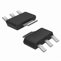
... HIGH CURRENT TRANSISTOR SURFACE MOUNT COLLECTOR 2,4 BASE 1 EMITTER 3 MARKING DIAGRAM 4 2 AYW 3 CEG G STYLE Specific Device Code A = Assembly Location Y = Year W = Work Week G = Pb−Free Package ORDERING INFORMATION † Package Shipping SOT−223 1000 / Tape & Reel (Pb−Free) Publication Order Number: BCP69T1/D ...

Page 2

ELECTRICAL CHARACTERISTICS Characteristics OFF CHARACTERISTICS Collector−Emitter Breakdown Voltage (I = −100 mAdc Collector−Emitter Breakdown Voltage (I = −1.0 mAdc Emitter−Base Breakdown Voltage (I = −10 mAdc Collector−Base Cutoff Current (V = − 25 Vdc, ...

Page 3

TYPICAL ELECTRICAL CHARACTERISTICS 0.35 0. 0.25 0.20 0.15 0.10 0.05 0 0.001 0. COLLECTOR CURRENT (A) C Figure 3. Collector Emitter Saturation Voltage vs. Collector Current 1.2 1.1 V 1.0 0.9 −55°C ...

Page 4

... PIN 1. BASE 2. COLLECTOR 3. EMITTER 4. COLLECTOR 6.3 mm inches ON Semiconductor Website: www.onsemi.com Order Literature: http://www.onsemi.com/orderlit For additional information, please contact your local Sales Representative BCP69T1/D MAX 0.068 0.004 0.035 0.126 0.014 0.263 0.145 0.094 0.041 −−− 0.078 0.287 ...

Related keywords