MPS2222ARLRM ON Semiconductor, MPS2222ARLRM Datasheet - Page 3
MPS2222ARLRM
Manufacturer Part Number
MPS2222ARLRM
Description
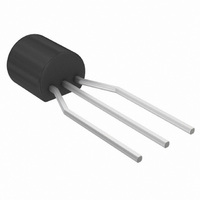
TRANSISTOR NPN GP SS 40V TO-92
Manufacturer
ON Semiconductor
Datasheet
1.MPS2222.pdf
(8 pages)
Specifications of MPS2222ARLRM
Transistor Type
NPN
Current - Collector (ic) (max)
600mA
Voltage - Collector Emitter Breakdown (max)
40V
Vce Saturation (max) @ Ib, Ic
1V @ 50mA, 500mA
Dc Current Gain (hfe) (min) @ Ic, Vce
100 @ 150mA, 10V
Power - Max
625mW
Frequency - Transition
300MHz
Mounting Type
Through Hole
Package / Case
TO-92-3 (Standard Body), TO-226
Lead Free Status / RoHS Status
Contains lead / RoHS non-compliant
Current - Collector Cutoff (max)
-
Available stocks
Company
Part Number
Manufacturer
Quantity
Price
Company:

Part Number:
MPS2222ARLRMG
Manufacturer:
ON
Quantity:
6 000


2. f T is defined as the frequency at which |h fe | extrapolates to unity.
ELECTRICAL CHARACTERISTICS
SMALL–SIGNAL CHARACTERISTICS
SWITCHING CHARACTERISTICS
Current–Gain – Bandwidth Product (Note 2.)
Output Capacitance (V CB = 10 Vdc, I E = 0, f = 1.0 MHz)
Input Capacitance
Input Impedance
Voltage Feedback Ratio
Small–Signal Current Gain
Output Admittance
Collector Base Time Constant
Noise Figure
Delay Time
Rise Time
Storage Time
Fall Time
(I C = 20 mAdc, V CE = 20 Vdc, f = 100 MHz)
(V EB = 0.5 Vdc, I C = 0, f = 1.0 MHz)
(I C = 1.0 mAdc, V CE = 10 Vdc, f = 1.0 kHz)
(I C = 10 mAdc, V CE = 10 Vdc, f = 1.0 kHz)
(I C = 1.0 mAdc, V CE = 10 Vdc, f = 1.0 kHz)
(I C = 10 mAdc, V CE = 10 Vdc, f = 1.0 kHz)
(I C = 1.0 mAdc, V CE = 10 Vdc, f = 1.0 kHz)
(I C = 10 mAdc, V CE = 10 Vdc, f = 1.0 kHz)
(I C = 1.0 mAdc, V CE = 10 Vdc, f = 1.0 kHz)
(I C = 10 mAdc, V CE = 10 Vdc, f = 1.0 kHz)
(I E = 20 mAdc, V CB = 20 Vdc, f = 31.8 MHz)
(I C = 100 mAdc, V CE = 10 Vdc, R S = 1.0 k , f = 1.0 kHz)
Figure 1. Turn–On Time
Characteristic
SWITCHING TIME EQUIVALENT TEST CIRCUITS
(T A = 25 C unless otherwise noted) (Continued)
MPS2222A only
(V CC = 30 Vdc, V BE(off) = –0.5 Vdc,
(V CC
I C = 150 mAdc, I B1 = 15 mAdc) (Figure 1)
(V CC = 30 Vdc, I C = 150 mAdc,
(V CC
I B1 = I B2 = 15 mAdc) (Figure 2)
Scope rise time < 4 ns
*Total shunt capacitance of test jig, connectors, and oscilloscope.
30 Vdc, V BE(off)
30 Vdc, I C
MPS2222, MPS2222A
http://onsemi.com
150 mAdc,
3
0.5 Vdc,
MPS2222A
MPS2222A
MPS2222A
MPS2222A
MPS2222A
MPS2222A
MPS2222A
MPS2222A
MPS2222A
MPS2222A
MPS2222A
MPS2222A
MPS2222
MPS2222
Figure 2. Turn–Off Time
Symbol
C obo
rb C c
C ibo
h oe
h re
h ie
h fe
NF
f T
t d
t s
t r
t f
0.25
Min
250
300
2.0
5.0
50
75
25
–
–
–
–
–
–
–
–
–
–
–
Max
1.25
300
375
200
150
225
8.0
8.0
8.0
4.0
4.0
30
25
35
10
25
60
–
–
X 10 –4
mmhos
MHz
Unit
k
pF
pF
dB
ps
ns
ns
ns
ns
–
Related parts for MPS2222ARLRM
Image
Part Number
Description
Manufacturer
Datasheet
Request
R

Part Number:
Description:
TRANS NPN SS GP 30V TO92
Manufacturer:
ON Semiconductor
Datasheet:
Part Number:
Description:
General Purpose Transistors NPN Silicon
Manufacturer:
On Semiconductor
Part Number:
Description:
ON Semiconductor [VOLTAGE REGULATOR]
Manufacturer:
ON Semiconductor
Datasheet:
Part Number:
Description:
357-036-542-201 CARDEDGE 36POS DL .156 BLK LOPRO
Manufacturer:
ON Semiconductor
Datasheet:
Part Number:
Description:
357-036-542-201 CARDEDGE 36POS DL .156 BLK LOPRO
Manufacturer:
ON Semiconductor
Datasheet:
Part Number:
Description:
357-036-542-201 CARDEDGE 36POS DL .156 BLK LOPRO
Manufacturer:
ON Semiconductor
Datasheet:
Part Number:
Description:
357-036-542-201 CARDEDGE 36POS DL .156 BLK LOPRO
Manufacturer:
ON Semiconductor
Datasheet:
Part Number:
Description:
357-036-542-201 CARDEDGE 36POS DL .156 BLK LOPRO
Manufacturer:
ON Semiconductor
Datasheet:
Part Number:
Description:
357-036-542-201 CARDEDGE 36POS DL .156 BLK LOPRO
Manufacturer:
ON Semiconductor
Datasheet:
Part Number:
Description:
357-036-542-201 CARDEDGE 36POS DL .156 BLK LOPRO
Manufacturer:
ON Semiconductor
Datasheet:
Part Number:
Description:
357-036-542-201 CARDEDGE 36POS DL .156 BLK LOPRO
Manufacturer:
ON Semiconductor
Datasheet:
Part Number:
Description:
357-036-542-201 CARDEDGE 36POS DL .156 BLK LOPRO
Manufacturer:
ON Semiconductor
Datasheet:
Part Number:
Description:
357-036-542-201 CARDEDGE 36POS DL .156 BLK LOPRO
Manufacturer:
ON Semiconductor
Datasheet:
Part Number:
Description:
Manufacturer:
ON Semiconductor
Datasheet: