4-1393766-4 TE Connectivity, 4-1393766-4 Datasheet - Page 5
4-1393766-4
Manufacturer Part Number
4-1393766-4
Description
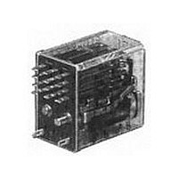
Electromechanical Relay DPDT 3A 24VDC 700Ohm Plug-In
Manufacturer
TE Connectivity
Type
General Purpose Relayr
Datasheet
1.4-1393766-4.pdf
(6 pages)
Specifications of 4-1393766-4
Contact Arrangement
DPDT
Dc Coil Voltage
24 V
Coil Current
34.28 mA
Mounting
Plug-In
Relay Construction
Non-Latching
Coil Voltage Dc
24V
Contact Form
2 Form C
Voltage Rating (vdc)
28V
Voltage Rating (vac)
120V
Coil Resistance
700Ohm
Pick-up Voltage (max)
18VDC
Operate Time
30ms
Contact Current Rating
3A
Contact Material
Silver
Coil Suppression Diode
No
Push To Test Button
No
Led Indicator
No
Seal
Unsealed
Product Depth (mm)
18.7mm
Product Length (mm)
24.13mm
Pin Count
8
Mounting Style
Plug-In
Termination Style
Solder Lug
Package / Case
Dust Cover
Lead Free Status / Rohs Status
Compliant


(8.13)
09-2010, Rev. 0910
www.te.com
© 2010 Tyco Electronics Ltd.
PCB layout
Bottom view on solder pins
Terminal Types E2 & R2
(Omit unnecessary holes)
.320
Product code structure
Type
Case style
Terminal and mounting
Contact style and rating
Number of poles
Coil voltage
(5.33)
.210
(2.79)
.110
R10
R10S Super sensitive cradle-style relay with form C contacts
E
R
T
1
2
6
7
9
W Single contact rated 7.5A max, 300mA min.
X
M Bifurcated contact rated 5A max, 300 mA min.
Y
Z
P
L
1
2
3
Coil code: please refer to coil versions table
AC voltage Specify coil code consisting of nominal coil voltage followed by W (example: 24V)
DC voltage Specify coil code consisting of coil adjustment code letter followed by coil resistance (example: V700)
2) Available only on 1 through 6 pole models
(10.16)
Non-sealed polycarbonate dust cover (RTI)
Wash-tight (RTIII), tape sealed plastic case
Octal style base on non-sealed polycarbonate dust cover (terminal types 1 & 2 only; 1, 2 & 3 poles only)
1) R10 type only, terminal code 2 or 9 only, no ground or stud
Solder/Plug-in terminals with #3-48 mounting stud on R10-E; 8-pin octal type on R10-T
PCB terminals (std.) 1.62mm (.064in) clearance, 31.75mm (1.25in) seated ht.; 11-pin octal type on R10-T
Side mounting plate with #6-32 stud, solder/plug-in terminals (#3-48 stud not included)
Narrow 1.02mm (.04in) PCB terminals, .33mm (.013in) clearance, 30.48mm (1.2in) seated ht.
Non-shouldered, narrow 1.02mm (.04in) PCB terminals in staggered arrangement
Single contact rated 5A max, 300mA min.
Single contact rated 2A typ, 3A max, 100mA min.
Bifurcated low level contacts rated 100mA typ, 2A max, 1mA min.
Bifurcated crossbar dry circuit contacts rated 1mA typ, 3A max, dry circuit min.
Bifurcated crossbar dry circuit contacts rated 500 microA typ, 250 mA max, dry circuit min.
3) Ratings are at 28VDCV or 115VAC. Total load must not exceed 30A per relay.
4) Use ungrounded frame for AC load of ≥5A. Max ratings are 7.5A at 115VAC and 4A at 28VDC for coil codes S & J
5) Only available on R10 type, only available with coil adjustment code V, Q, S and J.
6) Use ungrounded frame for AC load of ≥5A. Max ratings are 5A at 115VAC and 3A at 28VDC for coil codes S & J
1 pole
2 pole
3 pole
7) Not available with contact code W
8) Only available with case style E, not available with contact code W
(11.43)
.400
.450
Cradle-style relay with form C contacts
(13.97)
(10.67)
.550
.420
(
.056
1.42
(13.46)
HOLES
.530
+ .004
+ .10
- .000
- .00
(16.00)
3)
.630
(18.80)
.740
)
DIA.
General Purpose Relays
General Purpose Relays
General Purpose Relays
Industrial Relays
Industrial Relays
Industrial Relays
R10 Series Panel Plug-in Relay
.056
(
Datasheets and product specification ac-
cording to IEC 61810-1 and to be used only
together with the ‘Definitions’ section.
1.42
HOLES
Terminal Types E9 & R9
(Omit unnecessary holes)
+ .004
- .000
+ .10
- .00
(2.54)
GRID
.100
)
(12.70)
DIA.
.500
5) 6)
1)
4
6
8
(12.70)
(11.43)
4) 5)
.500
.450
5) 6)
4 pole (not available on R10-T)
6 pole (not available on R10-T)
8 pole (not available on R10-T)
(3.81)
POLE
.150
2
POLE
POLE
6
(2.54)
4
.100
Typical product code
Datasheets and product data is subject to the
terms of the disclaimer and all chapters of
the ‘Definitions’ section, available at
http://relays.te.com/definitions
Suggested panel cutout for relay
(16.66 ± .38)
.656 ± .015
(
2.77
.109
(Continued)
2 HOLES
+ .005
– .000
+ .13
– .00
(7.14)
.281
X =
)
7)
DIA.
8)
2 POLE – .343 ± .020
4 POLE – .562 ± .020
6 POLE – .781 ± .020
8 POLE – 1.000 ± .020
2)
(8.99)
.354
TOLERANCE:
(8.71 ± .51)
(14.27 ± .51)
(19.84 ± .51)
(25.40 ± .51)
(3.56)
.140
X
R10
± .010
(± .25)
.281 ± .015
(7.14 ± .38)
-E
Datasheets, product data, ‘Definitions’ sec-
tion, application notes and all specifications
are subject to change.
Potter & Brumfield
Potter & Brumfield
Potter & Brumfield
Mounting hole layout for
terminal & mounting style 6
.187 ± .0 02 DIA .
1
(4.75 ± .05)
.147 ± .0 02 DIA .
Y
(3.73 ± .05)
(11.10)
.437
4
-V700
5
Related parts for 4-1393766-4
Image
Part Number
Description
Manufacturer
Datasheet
Request
R

Part Number:
Description:
TERMINAL, FASTON, 6.35X0.81MM
Manufacturer:
TE Connectivity
Datasheet:

Part Number:
Description:
3.96 EP HDR ASSY 5P RED
Manufacturer:
TE Connectivity
Datasheet:

Part Number:
Description:
Heavy Duty Power Connectors HVT-C-Bu.Au.2 5 qmm
Manufacturer:
TE Connectivity
Datasheet:

Part Number:
Description:
WIRE-BOARD CONN, HEADER, 13WAY, 0.1IN
Manufacturer:
Tyco Electronics
Datasheet:

Part Number:
Description:
Conn IDC Connector F 13 POS 3.96mm IDT RA Cable Mount
Manufacturer:
TE Connectivity
Datasheet:

Part Number:
Description:
Conn IDC Connector F 13 POS 2.54mm IDT RA Cable Mount Loose Piece
Manufacturer:
TE Connectivity
Datasheet:
Part Number:
Description:
Conn IDC Connector F 13 POS 2.54mm IDT RA Cable Mount Loose Piece
Manufacturer:
TE Connectivity
Datasheet:

Part Number:
Description:
CONN BARRIER BLOCK 13POS 9.53MM
Manufacturer:
Tyco Electronics
Datasheet:

Part Number:
Description:
CONN HEADER VERT 13POS .100 TIN
Manufacturer:
Tyco Electronics
Datasheet:
Part Number:
Description:
CONN HEADR BRKWAY .100 13POS STR
Manufacturer:
Tyco Electronics
Datasheet:

Part Number:
Description:
Manufacturer:
TE Connectivity
Datasheet:

Part Number:
Description:
Manufacturer:
TE Connectivity
Datasheet:

Part Number:
Description:
RES 390 OHM 1W 5% 2512
Manufacturer:
TE Connectivity
Datasheet:
Part Number:
Description:
Electromechanical Relay 3PST-NO/SPST-NC 8A 24VDC 720Ohm Through Hole
Manufacturer:
TE Connectivity
Datasheet:
Part Number:
Description:
ADF08ST04=DIP SWT,FLUSH,SMT-GW
Manufacturer:
TE Connectivity
Datasheet: