3-747579-2 TE Connectivity, 3-747579-2 Datasheet
3-747579-2
Specifications of 3-747579-2
Available stocks


3-747579-2 Summary of contents
Page 1
... Dia. Holes Sockets (pgs. 100, 101) Clinch Nuts, 4-40 Threaded Dimensions are shown for USA: 1-800-522-6752 reference purposes only. Canada: 1-905-470-4425 Specifications subject Mexico: 01-800-733-8926 to change. C. America: 52-55-1106-0803 Contacts Termination Plating Duplex (.000030 [0.00076] Gold and Tin) Crimp Duplex Posted ...
Page 2
... Values in brackets www.tycoelectronics.com are metric equivalents. (Continued) Section Contents Plug and Receptacle Connectors . . . . . . . . . . . . . . . . . . . . . 92, 93 Basic Shielding Hardware Kits . . . . . . . . . . . . . . . . . . . . . . . . 94, 95 Shielding Hardware Enclosure Kits . . . . . . . . . . . . . . . . . . . 96, 97 Preassembled Shielded Connector Kits . . . . . . . . . . . . . . . . . . 98 Ferrules for Shielding Hardware Kits . . . . . . . . . . . . . . . . . . . . . . 99 Contacts . . . . . . . . . . . . . . . . . . . . . . . . . . . . . . . . . . . . . . . . . . . 100, 101 Application Tooling . . . . . . . . . . . . . . . . . . . . . . . . . . . . . . . . . . . . . . 102 ...
Page 3
... HDE—pages 110-123 HDP—pages 90-102 HD-20 Board Mount— pages 54-71, 78-85, 87-89 Mating/Panel Mounting—page 42 Cable Clamps—pages 132, 133, 135-137, 140, 141, 144, 145 Mating Hardware—pages 146-150, 153, 155 Technical Documents: Product Specification—108-40005 Application Specifications— ...
Page 4
... Shell Indents 205204-4 205203-8 205203-3 1658642-1 — 1658643-1 205206-3 205205-7 205205-2 5745908-2 — 1658644-1 207464-2 5205207-1 207463-1 5745036-2 207516-6 207516-5 205210-3 205209-7 205209-2 745135-4 — 5207661-3 1658641-2 1658640-2 1658640-1 5745883-2 — 5745884-1 South America: 55-11-2103-6000 Hong Kong: 852-2735-1628 Japan: 81-44-844-8013 UK: 44-8706-080-208 93 ...
Page 5
... Indents [5.84] [4.95] Typ. D .462 [11.73] Max. Dimensions are shown for USA: 1-800-522-6752 reference purposes only. Canada: 1-905-470-4425 Specifications subject Mexico: 01-800-733-8926 to change. C. America: 52-55-1106-0803 .120 Typ. 2 Holes Plug Connector Max. E Inside Outside Shield Shield Ferrule (Must Be Purchased Separately) View of Rear Shell ...
Page 6
... Clinch Nut .338-.480 .450 Standard 8.59-12.19 11.43 Dimensions are shown for USA: 1-800-522-6752 reference purposes only. Canada: 1-905-470-4425 Specifications subject Mexico: 01-800-733-8926 to change. C. America: 52-55-1106-0803 Typ. 2 Holes Rcpt. Connector Max. E Inside Shield Outside Shield Ferrule (Must Be Purchased Separately) View of Rear Shell ...
Page 7
... Cable Diameter Qty Max. Plug Connector HDP-20 Dimensions are shown for USA: 1-800-522-6752 reference purposes only. Canada: 1-905-470-4425 Specifications subject Mexico: 01-800-733-8926 to change. C. America: 52-55-1106-0803 F Max Cable Ref. D Max. 1.467 [37.26] .812 Typ. [20.62] Typ. South America: 55-11-2103-6000 Hong Kong: 852-2735-1628 ...
Page 8
... Notes: 1. Plugs accept size 20 DF pin contacts and receptacles accept size 20 DF socket contacts. ...
Page 9
... Performance Characteristics— page 41 Contacts—pages 100, 101 Application Tooling—page 102 Ferrules—page 99 Technical Documents: Product Specifications— 108-40005, 108-40030, 108-40032 Application Specifications— 114-10000 & 114-40030 Note: All part numbers are RoHS compliant. 98 Catalog 82068 Dimensions are in inches and ...
Page 10
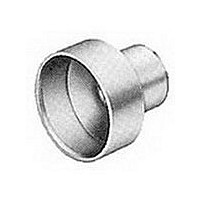
... Stepped 3-747579-0 11.18 5.51-6.25 .440 .246-.284 1-3 Stepped 3-747579-2 11.18 6.25-7.21 .440 .284-.324 1-3 Stepped 3-747579-2 11.18 7.21-8.23 .440 .324-.375 1-3 Stepped 3-747579-4 11.18 8.23-9.53 .440 .375-.437 1-3 Straight 2-747579-7 11.18 9.53-11.10 .440 ...
Page 11
... With Insulation Support Material and Finish: Pin—Brass Socket—Phosphor bronze Plated A—Select—Gold flash over nickel on entire contact, with additional .000030 [0.00076] gold on mating end B—Duplex—.000030 [0.00076] gold on Wire Size Range mating end, tin on termination end, with entire contact nickel underplated ...
Page 12
... Pin Diameter .040 [1.02] Snap-In Material and Finish: Pin—Brass Socket—Phosphor bronze Plated—Gold flash over nickel on entire contact, with additional .000030 [0.00076] gold on mating end Related Product Data: Performance Characteristics— 18 AWG Max. Wire (.046 [1.17] Max. Conductor Diameter) page 41 ...
Page 13
... Production rates 220 VAC Hz range up to 4800 leads per For further information hour for 3 [76.2] lengths. request Catalog 124324. The machine is micropro- cessor controlled, and pro - grammed and operated with Dimensions are shown for USA: 1-800-522-6752 reference purposes only. ...
Page 14
... C. America: 52-55-1106-0803 Contacts Plating Duplex (.000030 [0.00076] Gold and Tin) Crimp Duplex (Gold Flash and Tin) ➧ ➧ Duplex (0.000030 [0.00076] Gold and Tin) Crimp Duplex (Gold Flash and Tin) 103 South America: 55-11-2103-6000 Hong Kong: 852-2735-1628 Japan: 81-44-844-8013 UK: 44-8706-080-208 ...
Page 15
... Latching Blocks (pgs. 153, 154) Dimensions are shown for USA: 1-800-522-6752 reference purposes only. Canada: 1-905-470-4425 Specifications subject Mexico: 01-800-733-8926 to change. C. America: 52-55-1106-0803 (Continued) Contact bearing surface is large and symmetrical South America: 55-11-2103-6000 Hong Kong: 852-2735-1628 Japan: 81-44-844-8013 UK: 44-8706-080-208 ...
Page 16
... Related Product Data: Contact Arrangements—page 40 Performance Characteristics— page 41 Contacts—page 109 Ferrules—page 108 Mating/Panel Mounting —page 42 Cable Clamps—pages 132, 133, 135- 137, 140, 141, 144, 145 Mating Hardware—pages 146-150, 153, 155 No. of Technical Documents: Shell Contact ...
Page 17
... Components of the kits are shipped unassembled and bulk-packaged in quantities of 100 pieces. Dimensions are shown for USA: 1-800-522-6752 reference purposes only. Canada: 1-905-470-4425 Specifications subject Mexico: 01-800-733-8926 to change. C. America: 52-55-1106-0803 (Continued) Dia. Plug Connector C Ferrule (Must Be Purchased Separately) Dia. Rcpt. Connector C Max ...
Page 18
... Dimensions are shown for USA: 1-800-522-6752 reference purposes only. Canada: 1-905-470-4425 Specifications subject Mexico: 01-800-733-8926 to change. C. America: 52-55-1106-0803 (Continued) Cable E Max. Ref. .125 [3.18] Max. C Max. Cable E Max. Ref. .125 Max. [3.18] C Max. ...
Page 19
... Canada: 1-905-470-4425 Specifications subject Mexico: 01-800-733-8926 to change. C. America: 52-55-1106-0803 (Continued) L Part Numbers Ferrule Die Sets* 3-747579-0 543424-3 3-747579-0 543424-2 3-747579-0 543424-8 3-747579-2 543424-1 3-747579-2 543424-7 3-747579-4 543424-6 7-747579-7 543424-5 3-747579-6 543424-4 2-747580-4 543425-2 2-747580-3 543425-1 2-747580-1 58238-1 3-747580-1 58237-2 2-747580-2 58237-1 ...
Page 20
... All adjustments can be made from the front of the machine without special tools. Power requirement is 120 VAC. Air requirement is 80-100 psi [5.52-6.89 bar], 3.5 scfm [0.00165 m 3 /s]. For further information request Catalog 65004. Dimensions are shown for USA: 1-800-522-6752 reference purposes only ...
Page 21
... Flash snap-in contacts and Tin) available, see page 121 ➧ ➧ Duplex (.000030 [0.00076] Gold and Insulation Tin) Displacement Duplex * Interchangeable crimp (Gold Flash snap-in contacts and Tin) available, see page 121 South America: 55-11-2103-6000 Hong Kong: 852-2735-1628 Japan: 81-44-844-8013 UK: 44-8706-080-208 ...
Page 22
... All-Plastic Plug and Receptacle Connectors . . . . . . . 112, 113 Metal-Shell Plug and Receptacle Connectors . . . . . . 114, 115 Basic Shielding Hardware Kits . . . . . . . . . . . . . . . . . . . . . 116, 117 Shielding Hardware Enclosure Kits 118, 119 Ferrules for Shielding Hardware Kits . . . . . . . . . . . . . . . . . . . . 120 Interchangeable Contacts, Crimp Snap- 121 Application Tooling . . . . . . . . . . . . . . . . . . . . . . . . . . . . . . . . . 122, 123 Rate 7.4 Sec./Line 5 ...
Page 23
... HDE connectors are designed for terminating solid or stranded (7-strand max.) wire. 3. Individual conductor strands should be larger than .005 inch [0.127] diameter. 4. Extraction Tool Part No. 91232-1 (Instruction Sheet 408-6631) is used to remove pin or socket contacts. 5. For terminating more than one wire drain wire, use crimp contacts on page 121. ...
Page 24
... HDE connectors are designed for terminating solid or stranded (7-strand max.) wire. 3. Individual conductor strands should be larger than .005 inch [0.127] diameter. 4. Extraction Tool Part No. 91232-1 (Instruction Sheet 408-6631) is used to remove pin or socket contacts. 5. For terminating more than one wire drain wire, use crimp contacts on page 121. ...
Page 25
... HDE connectors are designed for terminating solid or stranded (7-strand max.) wire. 4. Individual conductor strands should be larger than .005 inch [0.127] diameter. 5. Extraction Tool Part No. 91232-1 (Instruction Sheet 408-6631) is used to remove pin or socket contacts. 6. For terminating more than one wire drain wire, use crimp contacts on page 121. ...
Page 26
... HDE connectors are designed for terminating solid or stranded (7-strand max.) wire. 4. Individual conductor strands should be larger than .005 inch [0.127] diameter. 5. Extraction Tool Part No. 91232-1 (Instruction Sheet 408-6631) is used to remove pin or socket contacts. 6. For terminating more than one wire drain wire, use crimp contacts on page 121. ...
Page 27
... Connector Insert—94V-0 rated thermoplastic, black Shield—Steel, tin plated Contacts—Phosphor bronze Contact Finish—Duplex plated: A—.000030 [0.00076] gold on mating end, tin on termination end, with entire contact nickel underplated B—Gold flash on mating end, tin on termination end, with entire contact ...
Page 28
... Connector Shell—Steel, tin plated Connector Insert—94V-0 rated thermoplastic, black Shield—Steel, tin plated Contacts—Phosphor bronze Contact Finish—Duplex plated: A—.000030 [0.00076] gold on mating end, tin on termination end, with entire contact nickel underplated B—Gold flash on mating end, tin on .490 [12.45] termination end, with entire contact Max ...
Page 29
... Expanding Neck Accommodates Cable Max. Contact Contact Cable Inner Finish I.D. No. 1 Outer Cable (Plating for 30-26 AWG for 26-22 AWG for 22-20 AWG Dia. Bundle Code) [0.05-0.15mm 2 ] [0.15-0.4mm Range Dia.† Plug A — .330 8.38 B — A — ...
Page 30
... Shield—Steel, tin plated Enclosure—PVC, black Jackscrews—Zinc alloy Contacts—Phosphor bronze Contact Finish—Duplex plated: A—.000030 [0.00076] gold on mating end, tin on termination end, with entire contact nickel underplated B—Gold flash on mating end, tin on termination end, with entire contact ...
Page 31
... Canada: 1-905-470-4425 Specifications subject Mexico: 01-800-733-8926 to change. C. America: 52-55-1106-0803 L Part Numbers Ferrule Die Sets* 3-747579-0 543424-3 3-747579-0 543424-2 3-747579-0 543424-8 3-747579-2 543424-1 3-747579-2 543424-7 3-747579-4 543424-6 2-747579-7 543424-5 3-747579-6 543424-4 2-747580-4 543425-2 2-747580-3 543425-1 2-747580-1 58238-1 3-747580-1 58237-2 2-747580-2 58237-1 ...
Page 32
... Technical Documents Code indicating accepted wire size range is stamped inside insulation crimp barrel of each contact. Product Specifications — Notes: 1. Extraction Tool No. 91232-1 is used to remove pin and socket contacts. 108-40011 2. Strip form contacts shipped 10,000 pieces/reel. 108-40030 Application Specifications— ...
Page 33
... This tool is manually actuated, using modular heads. Bench Mounted Bench Mount Tools with Pneumatic Power Assembly Modular Heads Bench Assembly No. 58338-1 Head Assembly No. 58063-2 This tool is air actuated with either a foot or knee switch. Note: All part numbers are RoHS compliant. 122 Catalog 82068 ...
Page 34
... No. 852423-1 Manual Arbor Tool Wire O.D. .041-.060 [1.04-1.52]—No. 543157-1 (tool mount), Wire O.D. .040 [1.02] and smaller—No. 543157-1 (tool mount), Note: All part numbers are RoHS compliant. Catalog 82068 Dimensions are in inches and Revised 1-08 millimeters unless otherwise specified ...
Page 35
... Thermoplastic, 94V-0, black in File No. E28476 Threaded Inserts—Brass, unplated R Contacts—Phosphor bronze, duplex CSA Certified in File ■ plated .000030 [0.00076] min. gold on R No.164196 (LR 7189) mating end, .000100-.000200 [0.00254- 0.00508] bright tin on termination end ■ UL Listed in File No. with entire contact underplated .000050 E81956, evaluated to [0 ...
Page 36
... Housing, Cover & Cable Stabilizer—Black thermoplastic, 94V-0 rated Threaded Inserts—Brass, unplated Pin Contacts—Phosphor bronze, duplex plated .000030 [0.00076] gold on mating end, .000100-.000200 [0.00254-0.00508] bright tin on termination end, with entire contact underplated .000050 [0.00127] nickel Related Product Data Contact Arrangement— ...
Page 37
... HDF-20 Plugs/Receptacles Mating and Panel Mounting Specifications Plug/Receptacle Mating Panel Cutouts .265 ±.015 ] Shell Sizes 1 & 2 [6.73 ±0.38 .256 ±.015 ] Shell Sizes 3, 4 & 5 [6.50 ±0.38 Plug Receptacle The .265/.256 [6.73/6.50] dimensions are required to assure full mating of connector halves. These dimensions must be taken ...
Page 38
... Revised 1-08 millimeters unless otherwise specified. Values in brackets www.tycoelectronics.com are metric equivalents. Hand Tool Kit No. 768340-1 Consists of a hand tool frame, a universal base assembly, a bench mount kit, and connector-specific tooling for AMP-LATCH Standard and Novo Receptacles, Card-Edge Connectors, and AMPLIMITE HDF-20 Connectors. ...
Page 39
... Anti-solderwicking contact design Intermateable with other ■ subminiature D connectors ■ Available in 9, 15, 25 and 37 position (shell sizes 1-4) plugs and receptacles Easy application without ■ special application tools ■ Shields offer full EMI shielding and ESD insulation ■ ...
Page 40
... HDF—pages 124-126 HDP—pages 90-101 Receptacle HD-20 Solder Cup—pages 128-130 HD-20 Board Mount—pages 54-71, 78-85, 87-89 Cable Clamps—pages 132, 133, 135, 136, 140, 141, 144, 145 Mating Hardware—pages 146-150, 151-154 Technical Documents: Product Specification 108-40031 Instruction Sheet ...
Page 41
... Related Product Data: Mateable Connectors: HDE—pages 110-119 2 HDF—pages 124-126 HDP—pages 90-101 HD-20 Solder Cup—pages 128-130 HD-20 Board Mount—pages 82-85, 87-89 3 Technical Documents: 4 Product Specification 108-40031 Note: Components of the kits are shipped unassembled and bulk-packaged in quantities of 100 pieces. ...
Page 42
... Unshielded Cable Clamps Universal Cable Clamps for Jacketed Cable . . . . . . . . . . . . 132 One-Piece, All-Plastic Cable Clamp 133, 134 Straight/90° Low Profile Cable Clamps . . . . . . . . . . . . . . . . . . 135 Slide-On Back Covers . . . . . . . . . . . . . . . . . . . . . . . . . . . . . . . . . . . 136 Box and Lid, Straight/90° Exit . . . . . . . . . . . . . . . . . . . . . . . . . . . 137 Clam Shell, Straight/45° 138 Straight Exit, Dataphone 139 Straight Exit for Jacketed Cable (Two-Piece 139 Straight/90° ...
Page 43
... HDE or HDP Plug or receptacle (Shown for Ref. only) Related Product Data: Connectors used with: HDE All-Plastic—pages 112 & 113 HDE Metal-Shell—pages 114 & 115 HDP Metal-Shell—pages 90-102 Other accessory capabilities: Spring Latches (Two Piece)— page 152 Technical Documents: Instruction Sheet— ...
Page 44
... HDE) (Quik-Snap) clamp kit designed for use with either the AMPLIMITE HDP-20, HDP-22, or HDE, all-plastic or metal-shell connectors. Kits are available for connector sizes and 4 with a cable exit option of 180° or 120°. Each kit contains: ■ 1-Hinged, plastic clamp ■ ...
Page 45
... Jacketed Cable, 180°/120° Exit and kit presents a complete HDP-20 and HDE-20 Connector package for your unshielded subminiature D connector needs. Kits are available for Shell Sizes 1, 2 and 3, and are packaged 25 and 100 kits per unit. Each kit contains: 1-Hinged Plastic Clamp 2-Retention Screws ...
Page 46
... Notes: 1. All parts are packaged unassembled. 2. Each kit is comprised of two cover halves (F and M) and an assortment of cable support gates. Latching Blocks—pages 153 & 154 3. Cable support gate must be used as shown for small diameter cable. 90° Exit Low Profile for Jacketed Cable Shell ...
Page 47
... Unshielded Cable Clamps Material Slide-On Back Covers Black thermoplastic Related Product Data: Connectors used with: HDE All-Plastic—pages 112 & 113 HDE Metal-Shell—pages 114 & 115 Other accessory capabilities: RFI/EMI Metal Shields— pages 141 & 142 Male Screw Retainers— ...
Page 48
... Female Screwlocks—page 148 Notes: 3. Cable clamp assemblies are available in kits with male screw retainers, see below. Locking Posts and Slide Latches— pages 149-151 Box and Lid Straight/90° Exit Cable Clamp Kits Spring Latches (Two Piece)— ...
Page 49
... Quantity of pan head screws supplied with cable clamp assembly varies with shell size. 3. Cable clamps are available in kits with male screw retainers, see below. 4. All pan head screws have combination cross-recessed and slotted heads. Male Screws mate with Female Screwlocks (See page 144 ...
Page 50
... Spring Latch (Two-Piece)— page 152 Notes: 1. All parts are packaged unassembled. 2. Jackscrews must be purchased separately. 3. Split-ring and crimp ferrules are shown on pages 143-145. Technical Documents: 4. Shielded cable clamps will not accept connector housings with clinch nuts. Instruction Sheet—408-6609 Note: All part numbers are RoHS compliant. ...
Page 51
... Material Black thermoplastic Related Product Data: Connectors used with: HDE All-Plastic—pages 112 & 113 HDE Metal-Shell—pages 114 & 115 HDP Metal-Shell—pages 90-102 Other accessory capabilities: Female Screwlocks—page 148 Locking Posts and Slide Latches— ...
Page 52
... Notes: 1. All parts are packaged unassembled. 2. Jackscrews must be purchased separately. Note: All part numbers are RoHS 3. Split-ring and crimp ferrules are shown on pages 143-145. compliant. 4. Shielded cable clamps will not accept connector housings with clinch nuts. Catalog 82068 Dimensions are in inches and ...
Page 53
... Jacketed Cable 108-40032 (Two-Piece) Instruction Sheet—408-6769 Shell Size * Cable Dia. with Grommet Kit: Size 2 = .185-.320 [4.70-8.13]; Size 3 = .255-.470 [6.48-11.94]. Notes: 1. All parts are packaged unassembled. Note: All part numbers are RoHS compliant. 142 Catalog 82068 Dimensions are in inches and ...
Page 54
... Canada: 1-905-470-4425 Specifications subject Mexico: 01-800-733-8926 to change. C. America: 52-55-1106-0803 AMP Hand Tool No. 543344-1 Die Set Numbers) Note: Split-ring ferrules cannot be used with outer and inner ferrules. Split-ring ferrules are suitable for both foil and braided shields. The ferrules do not require tooling for assembly ...
Page 55
... Continued on Page 145 South America: 55-11-2103-6000 Hong Kong: 852-2735-1628 Japan: 81-44-844-8013 UK: 44-8706-080-208 ...
Page 56
... Min. O.D. is .040 [1.02] smaller than Max. O.D. **For inner and outer ferrules, Min. O.D. is .050 [1.27] smaller than Max. O.D. At the Max. cable O.D. the Min. insulation thickness is .060 [1.52]. Note: Refer to page 143 for Application Tooling for ferrules. Note: All part numbers are RoHS compliant. ...
Page 57
... Each kit is comprised of two male screws and two retaining clips. Male screw retainers are also furnished as part of cable clamp kits (pages 137 and 138). 3. Male screw retainers mate with female screwlocks (page 144), with HDF metal-shell connectors featuring 4-40 threaded inserts (page 148) and with HD metal-shell board mount connectors featuring 4-40 threaded inserts or female screwlocks ...
Page 58
... Notes: 1. All parts are packaged unassembled. 2. Each kit is comprised of two male screws and two retaining clips. 3. Male screw retainers mate with female screwlocks (page 148), and with HD board mount connectors featuring female screwlocks. Notes: 4 ...
Page 59
... Integral Standoffs 2. Each female screwlock kit is comprised of two assemblies as illustrated above. 3. One or two flat washers may be required for panel thicknesses less than .060 [1.52]. Female screwlocks are not recommended for panel thicknesses greater than .060 [1.52]. 4. Female screwlocks with 2-56 thread size are to be used with cable clamps with mounting flanges. Female screwlocks with 4-40 and M3 (Metric) thread sizes can be used with all other cable clamps ...
Page 60
... Note 5.) [3.43] Plug or Receptacle (Shown for Ref. only) Flat Washer (2 Supplied) Lock Washer (2 Supplied) Hex Nut (2 Supplied) For Shell Sizes 2, 3 and 5 Dimensions are shown for USA: 1-800-522-6752 reference purposes only. Canada: 1-905-470-4425 Specifications subject Mexico: 01-800-733-8926 to change. C. America: 52-55-1106-0803 .165 [4 ...
Page 61
... Each kit is comprised of a slide latch and two screws, flat washers (if required), lock washers and hex nuts. Style I slide latches are also furnished as part of cable clamp kits (page 142). 3. Style I slide latches can be used with cable clamps that do not extend beyond the front flange of the con- nector or on connectors without cable clamps. ...
Page 62
... Notes: 1. All parts are packaged unassem- bled. 2. Each kit is comprised of two com- plete assemblies, as illustrated above. 3. For front panel mounting rec- ommended that a shim be used between the connector flange and — panel to prevent bowing of the flange. 4. Locking posts with 2-56 thread size are to be used with cable clamps with mounting flanges ...
Page 63
... Notes: 1. Two-piece spring latches can be used with RFI/EMI shields (pages 141). Notes: 2. Two-piece spring latches mate with latch- ing blocks (pages 153 & 154). A .920 [23.37] Typical Application of Two-Piece Spring Latches with Post Molded Strain Relief .170 [4.32] Min. ...
Page 64
... Each front panel latching block kit is comprised of two latching blocks. Two pan head screws of the appropriate length and thread size to be supplied by customer. Notes dimension .250 [6.35] is for connector flange mounting, .220 [5.59] is for use with .030 [0.76] thick panels, and .190 [4.83] is for use with .060 [1.52] thick panels. Notes: 4 ...
Page 65
... These latching blocks allow mounting screws to be installed thru the front of the block and to be screwed into the bracket of a right-angle connector, a fixed insert in a connector mounting flange nut behind the connector mounting flange (as illustrated above). 3. Latching blocks mate with spring latches (page 152). Typical Application of Rear-Panel Mounted Subminiature D Connector using Rear-Panel Latching Blocks ...
Page 66
... Metal-Shell or All-Plastic Receptacle (Shown for Ref. only) A .400 [10.16] .120 Dia. [3.05] (2 Holes ± .010 C [± 0.25 ] .010 [0.25] Ref. 9, 15, 25 and 37 Positions Dimensions A B .746 .984 18.95 24.99 1.074 1.312 27.28 33.32 1.614 1.852 41.00 47.04 2.266 2.500 57.56 63.50 ...