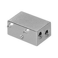
9-1469373-9 TE Connectivity, 9-1469373-9 Datasheet - Page 24

9-1469373-9
Manufacturer Part Number
9-1469373-9
Description
Connector Accessories Guide Module Zamak Nickel Over Copper Finish
Manufacturer
TE Connectivity
Type
Guide Moduler
Series
Advanced ATCAr
Datasheet
1.1-1469372-1.pdf
(52 pages)
Specifications of 9-1469373-9
Accessory Type
Guide Module
No. Of Positions
2
Body Material
Zinc Alloy
Mounting Type
Right Angle
Rohs Compliant
Yes
Number Of Positions / Contacts
40
Mounting Angle
Right
Mounting Style
Through Hole
Termination Style
Solder Pin
Housing Material
Thermoplastic
Contact Plating
Matte Tin
Product Type
Accessory
Mount Angle
Right Angle
Finish
Nickel
Location
Front Board
Keyed Position
None
Contact Plating, Mating Area, Material
Nickel over Copper
Inserts
Without
Version
K1/K2
Rohs/elv Compliance
RoHS compliant, ELV compliant
Lead Free Solder Processes
Not relevant for lead free process
Rohs/elv Compliance History
Always was RoHS compliant
Application
AdvancedATCA
For Use With
AdvancedATCA Connectors
Lead Free Status / Rohs Status
Details
1 This is the UL rating for an individual power contact. Current rating for any given configuration with multiple contacts will depend on contact layout, quantity
Contact Current Ratings
The graph to the right shows the current carrying capabili-
ties of an individual power contact,and that of multiple
contacts at 4.5, 6.0 and 7.5 mm contact spacing.
Safety Regulatory Agency Compliance
MINIPAK connectors have been evaluated and found to
comply with the UL1977 standard and the CSA standard
C22.2 No.182.3-M1987. Tyco Electronics will work with
customers to obtain application-specific regulatory certifi-
cations if needed.
Connector Mounting
Catalog 1773096
Revised 2-10
www.tycoelectronics.com
Surface Ref.
PC Board
Material
Insulators
Socket contacts
Signal pins
Power blades
Plating
Contacts
Terminals
Environmental/Mechanical
Connector operating temperature range
Mating forces
Electrical
Contact current rating
Voltage ratings
Insulation resistance
Dielectric strength
and spacing.
for .093" min. thick PCB
Compliant Press-fit
[4.06 – 5.08]
.160 – .200
.180 ± .020
4.57 ± 0.51
Long Tail
Dimension “A”
Dimensions are in inches and
millimeters unless otherwise
specified. Values in brackets
are metric equivalents.
Surface Ref.
PC Board
.120 ± .020
3.07 ± 0.51
Short Tail
Power Connectors & Interconnection Systems
MINIPAK High-Density Board-to-Board Power Connectors
Termination Tails
PPA, UL 94V-0 flammability rated, color black
Phosphor bronze alloy
Brass alloy
Copper alloy
Selective 30 microinches gold over nickel
Tin over nickel
-40°C to +130°C
Power: 1.5lb/contact typical
Signal: 0.2lb/contact typical
Individual power contact: 65A max.
AC Power: 125/250VAC, signal & DC power: up to 60V
5000Ω at 500V DC for 2 minutes, per MIL-STD 1344, Method 3003
Power 1,500VAC, signal 250VAC; for 1 minute, per MIL-STD 1344, Method 3001
Solder Tail
C
A
®
Dimensions are shown for
reference purposes only.
Specifications subject
to change.
US
1
100
10
70
50
90
80
60
40
30
20
0
USA: 1-800-522-6752
Canada: 1-905-470-4425
Mexico: 01-800-733-8926
C. America: 52-55-1106-0803
1
2
3
4
20A
4.5 mm contact spacing
6.0 mm contact spacing
7.5 mm contact spacing
Individual contact
[2.68]
.106
30A
Mating Condition
CURRENT (A)
40A
South America: 55-11-2103-6000
Hong Kong: 852-2735-1628
Japan: 81-44-844-8013
UK: 44-(0)8002-67666
(Continued)
50A
60A
[25.40]
1.000
2
3
4
1
33


