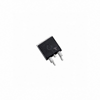
Q6025N5TP Littelfuse / Teccor Brand Thyristors, Q6025N5TP Datasheet - Page 6

Q6025N5TP
Manufacturer Part Number
Q6025N5TP
Description
TRIAC 600V 25A TO-263
Manufacturer
Littelfuse / Teccor Brand Thyristors
Specifications of Q6025N5TP
Triac Type
Standard
Mounting Type
Surface Mount
Configuration
Single
Current - Hold (ih) (max)
100mA
Voltage - Off State
600V
Current - Gate Trigger (igt) (max)
50mA
Current - Non Rep. Surge 50, 60hz (itsm)
167A, 200A
Current - On State (it (rms)) (max)
25A
Voltage - Gate Trigger (vgt) (max)
2.5V
Package / Case
TO-263-3, D²Pak (2 leads + Tab), TO-263AB
Current - On State (it (rms) (max)
25A
Lead Free Status / RoHS Status
Lead free / RoHS Compliant
Qxx25xx & Qxx25xHx Series
Soldering Parameters
Reflow Condition
Pre Heat
Average ramp up rate (Liquidus Temp)
(T
T
Reflow
Peak Temperature (T
Time within 5°C of actual peak
Temperature (t
Ramp-down Rate
Time 25°C to peak Temperature (T
Do not exceed
Physical Specifications
Terminal Finish
Body Material
Lead Material
Design Considerations
Careful selection of the correct device for the application’s
operating parameters and environment will go a long way
toward extending the operating life of the Thyristor. Good
design practice should limit the maximum continuous
current through the main terminals to 75% of the device
rating. Other ways to ensure long life for a power discrete
semiconductor are proper heat sinking and selection of
voltage ratings for worst case conditions. Overheating,
overvoltage (including dv/dt), and surge currents are
the main killers of semiconductors. Correct mounting,
soldering, and forming of the leads also help protect
against component damage.
S(max)
L
) to peak
to T
L
- Ramp-up Rate
- Temperature Min (T
- Temperature Max (T
- Time (min to max) (t
- Temperature (T
- Temperature (t
25 Amp Standard & Alternistor (High Commutation) Triacs
p
)
P
)
100% Matte Tin-plated
UL recognized epoxy meeting flammability
classification 94V-0
Copper Alloy
L
L
)
) (Liquidus)
s(min)
s(max)
s
)
P
)
)
)
Pb – Free assembly
150°C
200°C
60 – 180 secs
5°C/second max
5°C/second max
217°C
60 – 150 seconds
260
20 – 40 seconds
5°C/second max
8 minutes Max.
280°C
Teccor
+0/-5
°C
Revised: May 10, 2010 09:33 PM
®
brand Thyristors
122
High Temperature
Voltage Blocking
Temperature Cycling
Biased Temp &
Humidity
High Temp. Storage
Low-Temp Storage
Thermal Shock
Autoclave
(Pressure Cooker Test)
Resistance to
Solder Heat
Solderability
Lead Bend
Environmental Specifications
T
T
S(max)
S(min)
25
T
T
Test
P
L
time to peak temperature
Please refer to http://www.littelfuse.com for current information.
t
MIL -STD-750: Method 1040, Condition A
Rated V
MIL -STD-750: Method 1051
-40°C to 125°C, 15-minute dwell,
100 cycles
EIA/JEDEC: JESD22-A101
320VDC, 85°C, 85%RH, 1008 hours
MIL -STD-750: Method 1031
150°C, 1008 hours
-40°C, 1008 hours
MIL -STD-750: Method 1056
0°C to 100°C, 5-minute dwell,
10-second transfer, 10 cycles
EIA/JEDEC: JESD22-A102
121°C, 100%RH, 2atm, 168 hours
MIL -STD-750: Method 2031
260°C, 10 seconds
ANSI/J-STD-002, Category 3, Test A
MIL -STD-750: Method 2036, Condition E
S
Specifications are subject to change without notice.
Preheat
Preheat
Specifications and Conditions
Ramp-up
Ramp-up
RRM
, 125°C, 1008 hours
t
t
P
L
Ramp-down
Ramp-do
Time
©2010 Littelfuse, Inc


