1-746610-4 TE Connectivity, 1-746610-4 Datasheet - Page 82
1-746610-4
Manufacturer Part Number
1-746610-4
Description
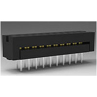
Conn IDC Connector M 16 POS 2.54mm IDT RA Cable Mount
Manufacturer
TE Connectivity
Type
IDC Connectorr
Series
AMP-LATCHr
Specifications of 1-746610-4
Pitch
2.54 mm
Number Of Rows
2
Number Of Contacts
16
Gender
M
Contact Plating
Gold Over Nickel
Termination Method
IDT
Connector Type
Wire To Board
Contact Termination
IDC / IDT
No. Of Contacts
16
No. Of Rows
2
Pitch Spacing
2.54mm
Rohs Compliant
Yes
Agency Approvals
CSA, UL
Angle
Straight
Brand/series
AMP-LATCH™
Color
Black
Current, Rating
1 A
Flammability Rating
UL94V-0
Length, Overall
0.98 "
Length, Pin
0.156 "
Material, Contact
Phosphor Bronze
Material, Dielectric
PVC (Cable)
Material, Housing
Thermoplastic
Mounting Hole Size
0.035 "
Pin Spacing
0.1 "
Primary Type
Interconnect System
Special Features
DIP Plug
Strain Relief
Low Profile
Temperature, Operating
-55 to +105 °C
Termination
Solder
Wire, Awg
28 AWG (Solid/Stranded)/26, 30 AWG (Solid)
Product Type
Plugs - PCB
Contact Gender
Pin (Male)
Number Of Positions / Contacts
16
Mounting Style
Through Hole
Termination Style
Solder Pin
Housing Material
Thermoplastic
Contact Material
Phosphor Bronze
Product Line
AMP-LATCH
Termination Method To Pc Board
Through Hole - Solder
Pcb Mounting Orientation
Vertical
Pcb Mount Retention
Without
Pcb Mount Alignment
Without
Termination Method To Wire/cable
IDC
Ul File Number
E28476
Csa File Number
LR 7189
Contact - Rated Current (a)
1
Operating Voltage Reference
AC
Operating Voltage (vac)
250
Wire/cable Size (awg)
26 – 30
Wire/cable Size (mm²)
0.051 – 0.15
Wire/cable Size (cma)
101 – 296
Tail Length (mm [in])
3.96 [0.156]
Tail Orientation
In-line
Profile Height (y-axis) (mm [in])
6.43 [0.253]
Number Of Positions
16
Centerline (mm [in])
2.54 [0.100]
Row-to-row Spacing (mm [in])
2.54 [0.100]
Length (x-axis) (mm [in])
24.89 [0.9799]
Width (z-axis) (mm [in])
7.06 [0.278]
Contact Type
Pin
Contact Base Material
Phosphor Bronze
Contact Plating, Mating Area, Material
Gold or Palladium Nickel or Performance Based
Contact Plating, Mating Area, Thickness (µm [?in])
2.54 [100]
Tail Plating Material
Tin
Tail Plating, Thickness (µm [?in])
2.54 [100]
Connector Style
Plug
Housing Color
Black
Ul Flammability Rating
UL 94V-0
Rohs/elv Compliance
RoHS compliant, ELV compliant
Lead Free Solder Processes
Wave solder capable to 240°C, Wave solder capable to 260°C, Wave solder capable to 265°C
Rohs/elv Compliance History
Always was RoHS compliant
Agency/standard
UL, CSA
Ul Rating
Recognized
Ul Voltage Rating (vac)
250
Operating Temperature (°c [°f])
-65 – +105 [-85 – +221]
Applies To
Printed Circuit Board
Accepts Wire Insulation Diameter, Range (mm [in])
0.81 – 1.07 [0.032 – 0.042]
Pcb Thickness, Recommended (mm [in])
3.18 [0.125]
Application Use
Wire-to-Board
Contact Transmits (typical Application)
Signal (Data)
Packaging Method
Tube
Lead Free Status / Rohs Status
RoHS Compliant part


2
Note: All part numbers are RoHS compliant.
(Soldertail
Length)
Dim. C
.102
2.59
.165
4.19
No. of
Pos.
10
14
16
20
24
26
30
34
40
50
60
10
14
16
20
24
26
34
40
50
1.250 [31.75]
1.450 [36.83]
1.550 [39.37]
1.750 [44.45]
2.050 [52.07]
2.250 [57.15]
2.450 [62.23]
2.750 [69.85]
3.250 [82.55]
3.750 [95.25]
1.250 [31.75]
1.450 [36.83]
1.550 [39.37]
1.750 [44.45]
2.050 [52.07]
2.450 [62.23]
2.750 [69.85]
3.250 [82.55]
1.950[49.53]
1.950[49.53]
A
Dimensions
View for Clarity
[8.89]
[8.89]
Eject Latches
Not Shown in
Top and Side
.350
.350
[0.33]
[8.89
.013
.350
Position #1 Indicator
Position #1 Indicator
1.100 [27.94]
1.200 [30.48]
1.400 [35.56]
1.600 [40.64]
1.900 [48.26]
2.400 [60.96]
2.900 [73.66]
1.100 [27.94]
1.200 [30.48]
1.600 [40.64]
1.900 [48.26]
2.400 [60.96]
[0.33]
[0.33]
+ .005
– .010
+ 0.13
– 0.25
.400 [10.16]
.600 [15.24]
.700 [17.78]
.900 [22.86]
.400 [10.16]
.600 [15.24]
.700 [17.78]
.900 [22.86]
.013
.013
]
B
Pin 2
1-1761693-1
1-1761693-6
Pin Header
[0.63
.025
1761693-3
1761693-8
1761694-3
1761694-9
Latches
without
—
—
—
—
—
—
—
—
—
—
—
—
—
—
± .001
± 0.03
[2.54]
Without Latches
.100
With Latches
]
Pin 1
Recommended PC Board Layout
A
A
B
U
U
U
U
Pin Header with Short Latches
[0.63
.025
(Mates with Receptacles
without Strain Relief)
± .001
± 0.03
Ø .035
[0.89
1-1761685-0
1-1761685-1
1-1761685-3
1-1761685-5
1-1761685-6
1-1761687-1
1-1761687-3
]
1761685-3
1761685-6
1761685-7
1761685-8
1761685-9
1761687-3
1761687-7
1761687-9
± .003
± 0.08
—
—
—
—
—
]
[14.62
[10.64
.576
.419
Part Numbers
[2.54]
± .006
± .006
.100
± 0.15
± 0.15
[20.98
[16.89
.826
.665
[6.40
[2.54]
]
]
.100
.252
Long
Short
± .020
± .020
± 0.51
± 0.51
+ .010
– .004
+ 0.25
– 0.10
Pin Header with Long Latches
]
]
[0.63
.025
Long
Short
(Mates with Receptacles
]
Ø .031
with Strain Relief)
[0.79]
± .001
± 0.03
Max.
1-1761686-1
1-1761686-3
1-1761686-5
1-1761688-1
1-1761688-5
Section U-U
]
1761686-3
1761686-5
1761686-6
1761686-7
1761686-8
1761686-9
1761688-7
1761688-8
1761688-9
—
—
—
—
—
—
C
[
[6.10
± .015
± 0.38
.240
± .010
± 0.25
]
]
Related parts for 1-746610-4
Image
Part Number
Description
Manufacturer
Datasheet
Request
R

Part Number:
Description:
IC SINGLE 3-IN AND GATE SC-74
Manufacturer:
NXP Semiconductors
Datasheet:
Part Number:
Description:
IC CONFIG MULTI-FUNC GATE SC-74
Manufacturer:
NXP Semiconductors
Datasheet:

Part Number:
Description:
IC SINGLE 2-IN AND GATE SC-74
Manufacturer:
NXP Semiconductors
Datasheet:

Part Number:
Description:
Operational Amplifiers - Op Amps Low-Power Rail-Rail I/O
Manufacturer:
Maxim Integrated
Datasheet:

Part Number:
Description:
Operational Amplifiers - Op Amps OPAMP 20MHZ VFB 120V/US 8CAN MIL
Manufacturer:
Intersil

Part Number:
Description:
Manufacturer:
TE Connectivity
Datasheet:

Part Number:
Description:
INSERT, MALE, SCREW, 16-32
Manufacturer:
TE Connectivity
Datasheet:

Part Number:
Description:
INSERT, FEMALE, SCREW TERM, 16-32WAY
Manufacturer:
TE Connectivity
Datasheet:

Part Number:
Description:
FFC/FPC CONNECTOR, RECEPTACLE 20POS 1ROW
Manufacturer:
TE Connectivity
Datasheet:

Part Number:
Description:
Conn D-Subminiature SKT 9 POS 2.74mm IDT ST Cable Mount 9 Terminal 1 Port
Manufacturer:
TE Connectivity
Datasheet:

Part Number:
Description:
HOUSING, SURFACE MOUNT, SIZE 1
Manufacturer:
TE Connectivity
Datasheet:

Part Number:
Description:
Conn D-Subminiature RCP 9 POS 2.74mm Solder ST Thru-Hole 9 Terminal 1 Port
Manufacturer:
TE Connectivity

Part Number:
Description:
FAST ISO-HUELSE6,3
Manufacturer:
TE Connectivity
Datasheet:
Part Number:
Description:
Manufacturer:
TE Connectivity
Datasheet:
Part Number:
Description:
Manufacturer:
TE Connectivity
Datasheet: