1-794066-0 TE Connectivity, 1-794066-0 Datasheet
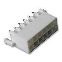
Conn Wire to Board PIN 12 POS 4.14mm Solder ST Thru-Hole

1-794066-0

Manufacturer Part Number
1-794066-0
Description
Conn Wire to Board PIN 12 POS 4.14mm Solder ST Thru-Hole
Manufacturer
TE Connectivity
Type
Wire to Boardr
Series
Mini-Universal MATE-N-LOK 2r
Datasheets

Specifications of 1-794066-0

Pitch
4.14 mm
Number Of Rows
2
Number Of Contacts
12
Gender
PIN
Contact Plating
Tin Over Nickel
Termination Method
Solder
Connector Type
Plug & Socket
Pitch Spacing
4.14mm
No. Of Contacts
12
No. Of Rows
2
Connector Mounting
PCB
Contact Material
Brass
Rohs Compliant
Yes
Product Type
Headers - Shrouded
Contact Gender
Pin (Male)
Number Of Positions / Contacts
12
Row Spacing
4.14 mm
Mounting Style
Through Hole
Mounting Angle
Vertical
Latching Type
Latched
Termination Style
Solder Pin
Housing Material
Nylon
Voltage Rating
600 V
Current Rating
9.5 A
Connector Line
Mini-Universal MATE-N-LOK, Mini-Universal MATE-N-LOK 2
Mount
Printed Circuit Board
Color
White
Pcb Mount Retention
With
Mount Angle
Vertical
Mating Retention Type
Detent Lock
Voltage (vac)
600
Current Rating (a)
9.5
Termination Post Length (mm [in])
3.68 [0.145]
Solder Tail Contact Plating
Matte Tin over Nickel
Centerline (mm [in])
4.14 [0.163]
Number Of Positions
12
Mating Retention
With
Contact Diameter (mm [in])
0.99 [0.039]
Pcb Mount Retention Type
Boardlock(s)
Contact Type
Pin
Contact Termination Type
Through Hole
Contact Layout
Double-Row
Contact Base Material
Brass
Contact Plating, Mating Area, Material
Matte Tin
Solder Process Drain Hole
With
Connector Style
Plug
Ul Flammability Rating
UL 94V-0
Rohs/elv Compliance
RoHS compliant, ELV compliant
Lead Free Solder Processes
Wave solder capable to 240°C, Wave solder capable to 260°C, Wave solder capable to 265°C
Rohs/elv Compliance History
Always was RoHS compliant
Applies To
Printed Circuit Board
Pcb Thickness, Recommended (mm [in])
1.57 [0.062]
Lead Free Status / Rohs Status
 Details

Available stocks

Company
Part Number
Manufacturer
Quantity
Price
Part Number:
1-794066-0
Manufacturer:
TE
Quantity:
20 000
1. INTRODUCTION
This specification covers the requirements for application of Mini- - Universal MATE- - N- -LOK connectors for
free- - hanging, panel- - mount, and printed circuit (pc) board applications. These connectors provide a reliable
and economic means of grouping multiple- -lead connections in computers, computer/peripheral equipment,
business machines, entertainment centers, and appliances.
The connectors are available in hermaphroditic housing and positively polarized: plug housing, vertical pin
header, right- -angle pin header, and cap housing. The housings accept socket contacts and pin contacts.
Each contact features a contact stop to ensure proper insertion depth of the contact in the contact cavity of the
housing. The contacts are available in strip form for machine application and loose piece for manual tooling
application.
The hermaphroditic housing is available with 2, 3, or 4 circuits for free- -hanging applications. The cap housing
is available in 1, 2, or 3 circuits for free- -hanging application and 2, 3, 4, 6, 9, 12, or 15 circuits for panel
mounting or free- -hanging application.
The plug housing and vertical pin header is available with 2, 3, 4, 6, 8, 9, 10, 12, 14, 15, 16, 18, 20, 22, or 24
circuits; the vertical blind- -mate pin header is available in 4, 6, 8, 9, 10, 12, or 15 circuits for panel mounting or
free- -hanging application. The right- -angle pin header is available in 2, 3, 4, 6, 8, 10, 12, 14, 16, 18, 20, 22, or
24 circuits for pc board application.
When corresponding with personnel, use the terminology provided in this specification to facilitate your
inquiries for information. Basic terms and features of this product are provided in Figure 1.
E2011 Tyco Electronics Corporation, a TE Connectivity Ltd. Company
All Rights Reserved
TE logo is a trademark.
*Trademark. Other product names, logos, or company names might be trademarks of their respective owners.
Locking
Tab
DANGER
NOTE
i
Hermaphroditic Housing
Cap Housing
All numerical values are in metric units [with U.S. customary units in brackets]. Dimensions are in millimeters [and
inches]. Unless otherwise specified, dimensions have a tolerance of +0.13 [+.005] and angles have a tolerance of +2_.
Figures and illustrations are for identification only and are not drawn to scale.
To avoid personal injury, these connectors are not to be used for interrupting current.
Locking
Latch
Mounting
Ear
Mini- Universal MATE- N- LOK* Connectors
Locking
Latch
Plug Housing
TOOLING ASSISTANCE CENTER 1- - 800- - 722- - 1111
PRODUCT INFORMATION 1- - 800- - 522- - 6752
Contact
Stop
Figure 1
Boardlock
Socket Contact
Vertical Pin Header
Locking
Lance
Solder
Tine
This controlled document is subject to change.
For latest revision and Regional Customer Service,
visit our website at www.te.com
Wire
Barrel
Insulation
Barrel
Standoff
Locking
Tab
Application Specification
Right- Angle Pin Header
114- - 16017
Pin Contact
17 MAR 11 Rev L
Solder
Tine
1 of 12
LOC B

Related parts for 1-794066-0

1-794066-0 Summary of contents

Page 1

... The plug housing and vertical pin header is available with 10, 12, 14, 15, 16, 18, 20, 22 circuits; the vertical blind- -mate pin header is available 10, 12 circuits for panel mounting or free- -hanging application. The right- -angle pin header is available 10, 12, 14, 16, 18, 20, 22 circuits for pc board application ...

Page 2

... The contacts accept stranded wire sizes AWG within the insulation diameter range listed in Figure 2. The wire insulation shall be stripped to a length from 3.20 to 3.71 [.126 to .146] for one- -wire crimping and 3.50 to 3.99 [.138 to .157] for two- - wire crimping. Reasonable care shall be taken not to nick, scrape, or cut any strands during the stripping operation. ...

Page 3

... Crimped or Deformed 0.25 [.010] Max Flash 0.50 [.020] Cutoff Tab Length Figure 2 (Cont’d) 114- - 16017 Insulation Barrel Formed Around But Not Cutting into Wire Insulation 0.10--0.51 [.004--.020] (Applicator) 0.10 [.004] Min (Hand Tool) Rear Bellmouth No Burrs on Cutoff Tab ...

Page 4

... Wires) 1.91 [.075] Max (2 Wires) D For tin- - coated 7- - strand wire size 26 AWG with 0.15 [.006] insulation diameter, crimp height must be controlled to +0.03/- - 0.05 [+.001/- - .002]. WIRE (Stranded Only) SIZE (AWG) INSULATION DIAMETER 30 28 1.52 [.060] Max ...

Page 5

... The wire must be pulled back lightly to ensure that the contact is locked in place. 3.4. Panel Mounting (Cap Housing) A. Thickness The panel thickness range shall be 0.79 through 2.01 [.031 through .079]. B. Cutout The dimensions of the panel cutout for panel mounting is provided in Figure 4. Rev L ...

Page 6

... PC Board (Vertical and Right- - Angle Pin Headers) A. Thickness The pc board thickness shall be 1.57 [.062]. Pc board thickness of 2.36 [.093] can also be used, but the plastic boardlock will function only as a press fit. B. Layout The pc board holes must be precisely located to ensure proper placement and optimum performance. ...

Page 7

... Rev L Vertical Pin Header 14--, 16--, 18--, 20--, 22--, and 24--Circuit, Dual Row 3.18 [.125] 4.44 [.175] 1.40¦0.08 Dia Dia [.055¦.003] Dia 4.14 [.163] Typ 4.14 [.163] Typ Right- Angle Pin Header « ...

Page 8

... Plc Figure 5 (End) 114- - 16017 « 1.40¦0.08 [.055¦.003] « 0.13 [.005 Plc 5.33 [.210] 20.70 [.815] « 1.40¦0.08 [.055¦.003] « 0.13 [.005 Plc 5 ...

Page 9

... Additionally, the flux must be compatible with the wave solder line, manufacturing, health, and safety requirements. Call the PRODUCT INFORMATION at the number at the bottom of page 1 for consideration of other types of flux. Fluxes that are compatible with these connectors are provided in Figure 6. ...

Page 10

... Strip- -form contacts are designed to be crimped with a miniature applicator installed in a semi- - automatic or automatic machine. Loose- - piece contacts are designed to be crimped with a hand crimping tool. AMP--O--LECTRIC Model “K” Terminating Machine 565435--5 can be used for terminating the contacts; however NOTE no longer being manufactured new. It has been superseded by AMP--O--LECTRIC Model “ ...

Page 11

... POWER UNIT 567418--1 122500--2, --3 or 356500--1, --2 567418--2 354500--1 or 565435--5 567066--3 122500--2, --3 or 356500--1, --2 567066--4 354500--1 or 565435--5 567067--1 122500--2, --3 or 356500--1, --2 567067 2 567067--2 354500 1 or 565435 5 354500--1 or 565435--5 567251--2 354500--1 or 565435--5 567251--3 354500--[ ] 567251 3 354500 [ ] ...

Page 12

... CUTOFF TAB MUST BE VISIBLE FRONT AND REAR BELLMOUTHS MUST BE VISIBLE LOCKING LATCHES AND TABS MUST BE SECURELY FASTENED STANDOFFS MUST BE VISUALLY SEATED ON PC BOARD FIGURE 10. VISUAL AID 114- - 16017 FREE- HANGING APPLICATION CABLE TIE MUST BE MINIMUM DISTANCE OF 76.2 [3.00] FROM WIRE END OF HOUSING Rev L ...

Related keywords