FP0805R1-R20-R Cooper/Bussmann, FP0805R1-R20-R Datasheet

Power Inductors 200nH 20A 2 PADS

FP0805R1-R20-R

Manufacturer Part Number
FP0805R1-R20-R
Description
Power Inductors 200nH 20A 2 PADS
Manufacturer
Cooper/Bussmann
Series
FP0805r
Datasheet

Specifications of FP0805R1-R20-R

Core Material
Ferrite
Product
Power Inductors
Test Frequency
100 KHz
Inductance
200 nH
Tolerance
10 %
Maximum Dc Current
20 Amps
Maximum Dc Resistance
0.17 mOhms
Dimensions
7.49 mm W x 7.62 mm L x 4.96 mm H
Shielding
Unshielded
Operating Temperature Range
- 40 C to + 125 C
Termination Style
SMD/SMT
Lead Free Status / RoHS Status
Lead free / RoHS Compliant

Available stocks

Company
Part Number
Manufacturer
Quantity
Price
Part Number:
FP0805R1-R20-R
Manufacturer:
Coiltronics/Div of Cooper/Buss
Quantity:
1 933
Part Number:
FP0805R1-R20-R
Manufacturer:
COOPER
Quantity:
20 000
High Current, High Frequency, Low-Profile Power Inductors
FLAT-PAC™ FP0805 Series
Description
• Halogen free
• 125°C maximum total temperature operation
• 7.5 x 7.6 x 5mm surface mount package
• Ferrite core material
• High current carrying capacity, Low core losses
• Controlled DCR tolerance for sensing circuits
• Inductance range from 32nH to 200nH
• Current range from 20 to 110 Amps
• Frequency range up to 2MHz
• RoHS compliant
1 Open Circuit Inductance (OCL) Test Parameters: 100kHz, 0.10V rms , 0.0Adc
2 Full Load Inductance (FLL) Test Parameters: 100kHz, 0.1V rms , I sat 1
3 I rms : DC current for an approximate temperature rise of 40°C without core loss. Derating is
1208
Part Number
FP0805R1-R03-R
FP0805R1-R06-R
FP0805R1-R07-R
FP0805R1-R10-R
FP0805R1-R20-R
SMD Device
SMD Device
necessary for AC currents. PCB pad layout, trace thickness and width, air-flow and proximity of
other heat generating components will affect the temperature rise. It is recommended the part
temperature not exceed 125°C under worst case operating conditions verified in the end
application.
BU-SB08859
7
OCL
1
± 10% (nH) FLL
100
200
32
58
72
2
144
Min. (nH)
23
42
52
72
I rms
Product Specifications
3
65
(Amps) I sat 1
4 I sat 1: Peak current for approximately 20% rolloff at +25°C.
5 I sat 2: Peak current for approximately 20% rolloff at +125°C.
6 K-factor: Used to determine B p-p for core loss (see graph). B p-p = K * L * ΔI * 10 -3 , B p-p : (Gauss),
7 Part Number Definition: FP0805Rx-Rxx-R
4
@ 25°C (Amps) I sat 2
Applications
• Multi-phase regulators
• Voltage Regulator Module (VRM)
• Point-of-load modules
• Desktop and server VRM’s and EVRD’s
• Data networking and storage systems
• Notebook regulators
• Graphics cards and battery power systems
• DCR sensing
Environmental Data
• Storage temperature range: -40°C to +125°C
• Operating temperature range: -40°C to +125°C (Range is application
• Solder reflow temperature: J-STD-020D compliant
Packaging
• Supplied in tape and reel packaging, 950 parts per reel,
K: (K-factor from table), L: (inductance in nH), ΔI (peak-to-peak ripple current in amps).
specific)
13 inch diameter reel.
110
Page 1 of 4
83
67
50
20
• FP0805 = Product code and size
• Rxx= Inductance value in μH, R = decimal point
5
@ 125°C (Amps) DCR (mΩ) @ 20°C K-factor
Data Sheet: 4340
95
61
49
35
16
0.17 ± 17%
• Rx is the DCR indicator
• “-R” suffix = RoHS compliant
823.6
823.6
823.6
823.6
823.6
6

Related parts for FP0805R1-R20-R

FP0805R1-R20-R Summary of contents

Page 1

... FP0805R1-R07-R 72 FP0805R1-R10-R 100 FP0805R1-R20-R 200 1 Open Circuit Inductance (OCL) Test Parameters: 100kHz, 0.10V rms , 0.0Adc 2 Full Load Inductance (FLL) Test Parameters: 100kHz, 0.1V rms , I sat rms : DC current for an approximate temperature rise of 40°C without core loss. Derating is necessary for AC currents. PCB pad layout, trace thickness and width, air-flow and proximity of other heat generating components will affect the temperature rise recommended the part temperature not exceed 125° ...

Page 2

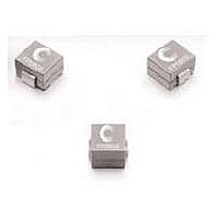
Top View Side View 4.96 max 7.49 max 1 0805Rx 7.62 max Rxx wwllyy ...

Page 3

Core Loss 10 1 0.1 0.01 0.001 0.0001 0.00001 100 Inductance Characteristics 100% 80% 60% 40% 20 20% 1208 BU-SB08859 Core Loss vs. B p-p 1000 B (Gauss) p ...

Page 4

Solder Reflow Profile T P Max. Ramp Up Rate = 3°C/s Max. Ramp Down Rate = 6°C Preheat A T smax T smin t s 25°C Time 25°C to Peak Reference JDEC J-STD-020D Profile Feature Preheat and Soak ...

Related keywords