CDSCB10M7GF123-R0 Murata Electronics North America, CDSCB10M7GF123-R0 Datasheet - Page 35
CDSCB10M7GF123-R0
Manufacturer Part Number
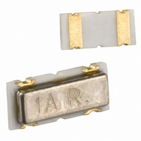
CDSCB10M7GF123-R0
Description
DISCR SMD FOR TOSHIBA TA31275
Manufacturer
Murata Electronics North America
Series
CDSCBr
Datasheets
1.CDSCB10M7GA042-R0.pdf
(1 pages)
2.CDSCB10M7GF123-R0.pdf
(16 pages)
3.CDSCB10M7GF123-R0.pdf
(73 pages)
Specifications of CDSCB10M7GF123-R0
Frequency
10.7MHz Center
Filter Type
Discriminator
Insertion Loss
3dB
Package / Case
0.177" L x 0.079" W x 0.039" H (4.50mm x 2.00mm x 1.00mm)
Mounting Type
Surface Mount
Lead Free Status / RoHS Status
Lead free by exemption / RoHS Compliant
Impedance
-
Bandwidth
-
Other names
490-4728-2
Available stocks
Company
Part Number
Manufacturer
Quantity
Price
Company:

Part Number:
CDSCB10M7GF123-R0
Manufacturer:
MURATA
Quantity:
36 000


!Note
• This PDF catalog is downloaded from the website of Murata Manufacturing co., ltd. Therefore, it’s specifications are subject to change or our products in it may be discontinued without advance notice. Please check with our
• This PDF catalog has only typical specifications because there is no space for detailed specifications. Therefore, please approve our product specifications or transact the approval sheet for product specifications before ordering.
sales representatives or product engineers before ordering.
!Note
Ceramic filter CFWLA series are low profile high
selectivity ceramic filters which use 6 elements in
ladder form.
They are best suitable to high-class transceivers,
cordless telephones and amateur radios.
1. Low profile, high selectivity
2. Available bandwidths are B to J as standard
3. Easily mountable on any PC board
4. Operating temperature range: -20 to +80 (degrees C)
S.S.G.
0dBm
CFWLA455KBFA-B0
CFWLA455KCFA-B0
CFWLA455KDFA-B0
CFWLA455KEFA-B0
CFWLA455KFFA-B0
CFWLA455KGFA-B0
CFWLA455KHFA-B0
CFWLA455KJFA-B0
For safety purposes, connect the output of filters to the IF amplifier through a D.C. blocking capacitor. Avoid applying a direct current to the output of ceramic filters.
The order quantity should be an integral multiple of the "Minimum Quantity" shown in package page in this catalog.
Ceramic Filters (CERAFILr) for Communications Equipment
CERAFILr Plastic Case General Use CFWLA Series
Features
Storage temperature range: -40 to +85 (degrees C)
Test Circuit
Rg
Part Number
• Please read rating and !CAUTION (for storage, operating, rating, soldering, mounting and handling) in this catalog to prevent smoking and/or burning, etc.
• This catalog has only typical specifications because there is no space for detailed specifications. Therefore, please approve our product specifications or transact the approval sheet for product specifications before ordering.
E1
R1
Rg+R1=R2=Input/Output Impedance
(1) (2) (3) (4)
Nominal Center
Frequency (fn)
(5)
455.0
455.0
455.0
455.0
455.0
455.0
455.0
455.0
(kHz)
R2
Bandwidth
fn 15.0
fn 12.5
fn 10.0
fn 7.5
fn 6.0
fn 4.5
fn 3.0
fn 2.0
(kHz)
min.
min.
min.
min.
min.
min.
min.
min.
6dB
E2
fn 30.0 max.
[within 50dB]
fn 24.0 max.
[within 50dB]
fn 20.0 max.
[within 50dB]
fn 15.0 max.
[within 50dB]
fn 12.5 max.
[within 50dB]
fn 10.0 max.
[within 50dB]
[within 50dB]
[within 50dB]
fn 9.0 max.
fn 7.5 max.
Bandwidth
(2)(3)(4) : Ground
RF Voltmeter
Connection
(kHz)
Stop
(5) : Output
(1) : Input
[within fn 100kHz]
[within fn 100kHz]
[within fn 100kHz]
[within fn 100kHz]
[within fn 100kHz]
[within fn 100kHz]
[within fn 100kHz]
[within fn 100kHz]
Attenuation
Stop Band
35 min.
35 min.
35 min.
35 min.
35 min.
35 min.
60 min.
60 min.
(dB)
[at minimum loss point]
[at minimum loss point]
[at minimum loss point]
[at minimum loss point]
[at minimum loss point]
[at minimum loss point]
[at minimum loss point]
[at minimum loss point]
Insertion
4.0 max.
4.0 max.
4.0 max.
6.0 max.
6.0 max.
6.0 max.
6.0 max.
7.0 max.
Loss
(dB)
2.3 0.5
2.9 0.3
0.15
(4) (3)
(5)
MARKING
11.0 0.5
[within fn 1.5kHz]
[within fn 10kHz]
2.9
2.9— — 0.3
2.9 0.3
[within fn 8kHz]
[within fn 7kHz]
[within fn 5kHz]
[within fn 4kHz]
[within fn 3kHz]
[within fn 2kHz]
2.0 0.3
(2)
EIAJ
CODE
0.3
3.0 max.
3.0 max.
3.0 max.
3.0 max.
3.0 max.
2.0 max.
2.0 max.
2.0 max.
Ripple
(1)
(dB)
2.6 0.3
1.2 0.5
Input/Output
Impedance
Connection
(2)(3)(4) : Ground
0.6 0.1
0.8 0.1
(ohm)
1500
1500
1500
1500
2000
2000
2000
2000
(1) : Input
(5) : Output
(in mm)
33
P05E.pdf
11.1.11
10
Related parts for CDSCB10M7GF123-R0
Image
Part Number
Description
Manufacturer
Datasheet
Request
R

Part Number:
Description:
BUZZER PIEZO 25VP-P SMD
Manufacturer:
Murata Electronics North America

Part Number:
Description:
CAP 4-ARRAY 680PF 100V X7R 1206
Manufacturer:
Murata Electronics North America
Datasheet:
Part Number:
Description:
CAP 4-ARRAY 1000PF 100V X7R 1206
Manufacturer:
Murata Electronics North America
Datasheet:
Part Number:
Description:
CAP 4-ARRAY 1800PF 100V X7R 1206
Manufacturer:
Murata Electronics North America
Datasheet:
Part Number:
Description:
CAP 4-ARRAY 68000PF 16V X7R 1206
Manufacturer:
Murata Electronics North America
Datasheet:

Part Number:
Description:
CAP CER 1000PF 50V 10% X7R 0402
Manufacturer:
Murata Electronics North America
Datasheet:
Part Number:
Description:
CAP CER 10000PF 16V 10% X7R 0402
Manufacturer:
Murata Electronics North America
Datasheet:

Part Number:
Description:
CAP 5.5-25PF 2.5X3.2MM SMD
Manufacturer:
Murata Electronics North America
Datasheet:

Part Number:
Description:
CAP 4.5-20PF 2.5X3.2MM SMD
Manufacturer:
Murata Electronics North America
Datasheet:

Part Number:
Description:
CAP 5.0-20PF 3.2X4.5MM SMD RED
Manufacturer:
Murata Electronics North America
Datasheet:

Part Number:
Description:
CAP 2.0-6.0PF 3.2X4.5MM SMD BLU
Manufacturer:
Murata Electronics North America
Datasheet:

Part Number:
Description:
CAP 1.4-3.0PF 3.2X4.5MM SMD BRN
Manufacturer:
Murata Electronics North America
Datasheet:

Part Number:
Description:
CAP 3.0-10PF 3.2X4.5MM SMD WHT
Manufacturer:
Murata Electronics North America
Datasheet:

Part Number:
Description:
CAP 2.0-6.0PF 4X4.5MM TOPADJ BLU
Manufacturer:
Murata Electronics North America
Datasheet:

Part Number:
Description:
CAP 8.5-40PF 4X4.5MM TOPADJ YEL
Manufacturer:
Murata Electronics North America
Datasheet: